Week 4 Challenge
1.Calculate dead load in design report based on IS code and apply dead load on the model
- Finishes of 50mm
- Slab as per design
- Brickwall 150mm thickness
- Roofing load based on purlin size
- Ceiling loading 0f 0.3KN per sq m
Ans)
Aim: To calculate dead load in the design report based on IS code and apply dead load on the model.
Tools Required:
->Manage Properties
->Slabs
->Properties tab
->Load
->Load cases
->Dead load
->Imposed load
->Area
->Full UDL
->Line
->Validation
Calculations:
DEAD LOAD :
Slab load = Model slab in software.
Finishes loading (50THK) = 0.05m x 24 KN/m^3 = 1.2 KN/m^2.
Brick wall with cement plaster thickness = 150mm.
Unit weight = 20 KN/m^3
Floor height (GF to FF) = 5.2 m
Brick wall loading = 15.6 KN/m
Floor height (FF to Roof) = 6.8 m
Brick wall loading = 20.4 KN/m
Roof loading = 1.5 KN/m^2
Procedure:
- Firstly, open the file which was created earlier.
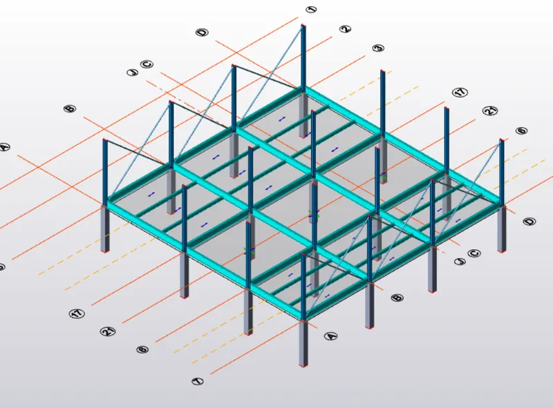
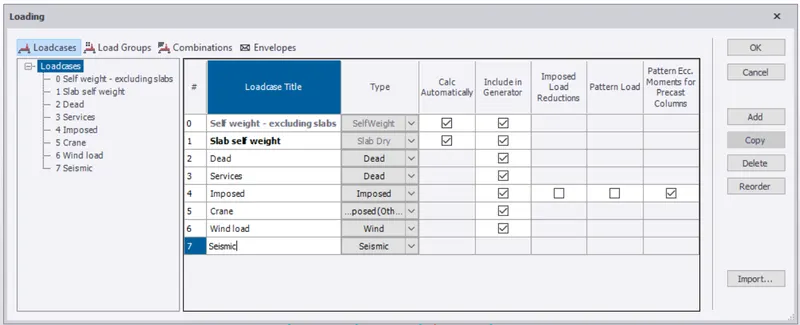
- Go to the load tab and select the load cases option under that, the Load cases dialog box appears.
- Create new loads such as crane, seismic and wind load to the list of predefined loads.
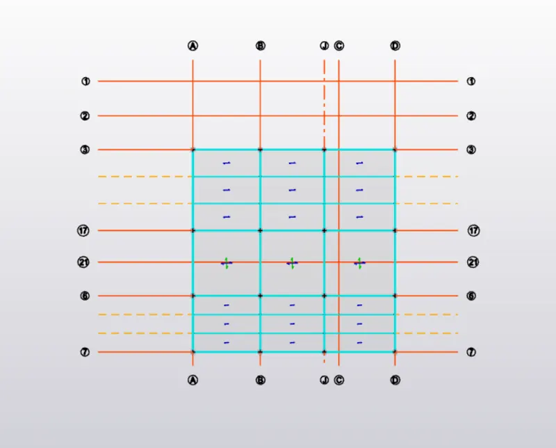
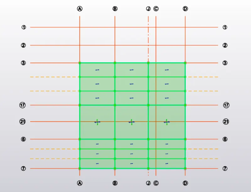
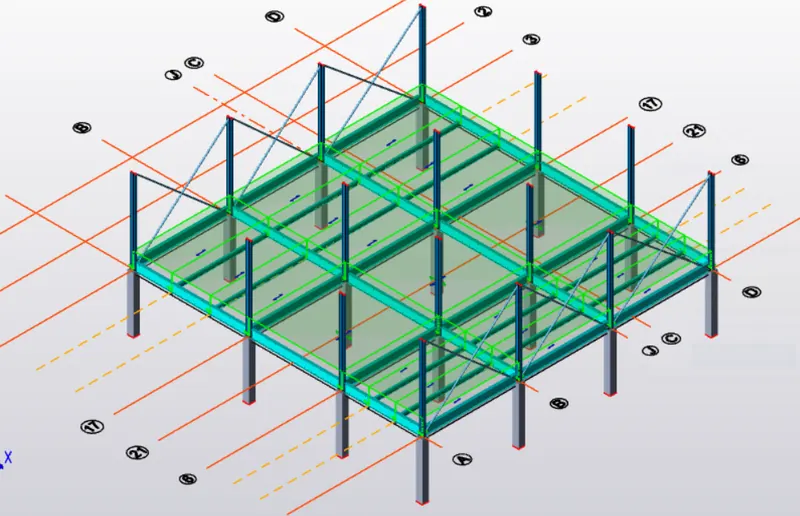
- Now we have to create slabs for all the layers required.
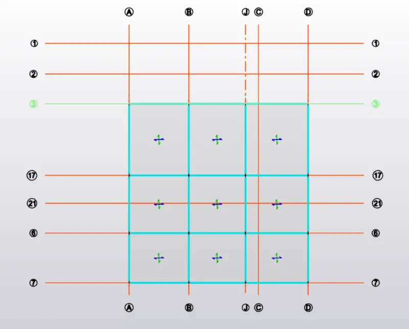
- Based upon the dimension of the adjacent beams we have to select one-way or two-way slabs, that is to select the two-way option when the ratio between the values is less than 2 else select the one-way slab itself.
- Also while adding the slab do create slab S1 with one way and S2 with two way the major changes among the S1 and S2 is nothing but this itself.
- Now the parameters are select the bar type 10, bar spacing as 150mm, over depth as 200mm, and the grade as M25.
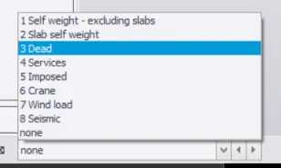
- Now at the bottom of our workspace, we find a dead load option in the drop-up dialog box.
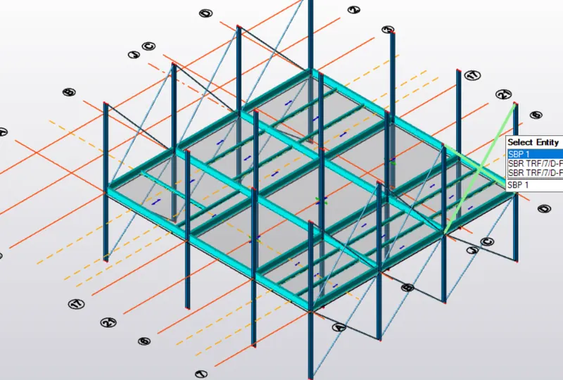
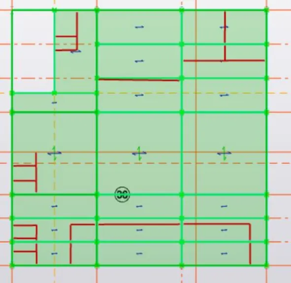
- Under the load tab, we have to select the area and give the value of 1.2KN/m square and select all the slabs.
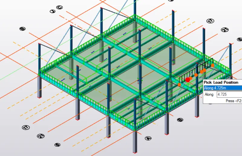
- Now we have to select Full UDL and apply the dead load to all the beams.
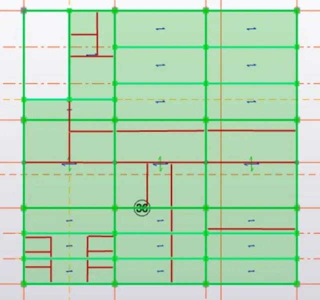
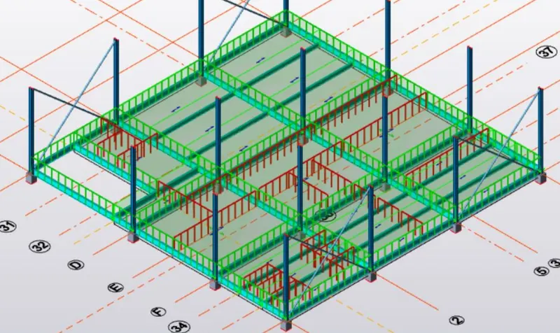
- Now select the Line tool under the load tab and draw the load of the wall in all the required floors.
- Do not forget to validate your model now and then to check your errors and correct them.
Result:
Hence, by following the above procedure, we will provide the dead loads to the slabs and beams for the structure.
_______________________________________________________________________________________________________________________________________________________
2.Calculate live load in design report based on IS code and apply live load on the model
- Assume the loading based on IS 875
- Roof loading
- Consider equipment loading as 5KN per sq m
Ans)
Aim: To calculate live load in the design report based on IS code and apply live load on the model.
Tools Required:
->Load
->Load cases
->Dead load
->Area.
Procedure:
- Firstly, open the file in which the dead loads were added.
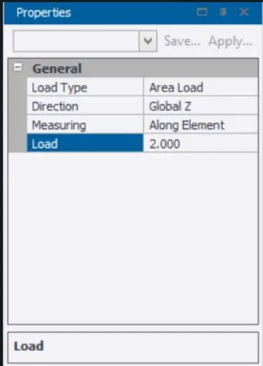
- Now at the bottom of our workspace, we find imposed load option in the drop-up dialog box.
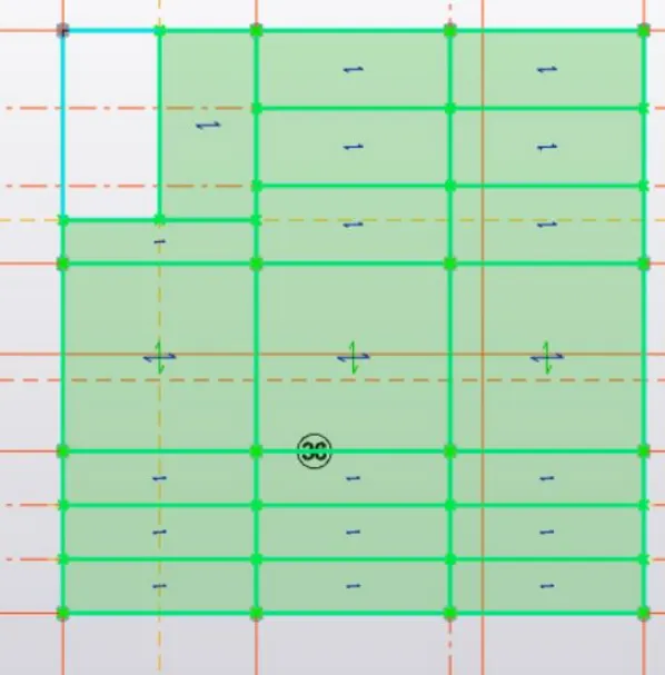
- Now we can provide live loads to the structure by selecting the load and assigning the value for it according to the IS Code.
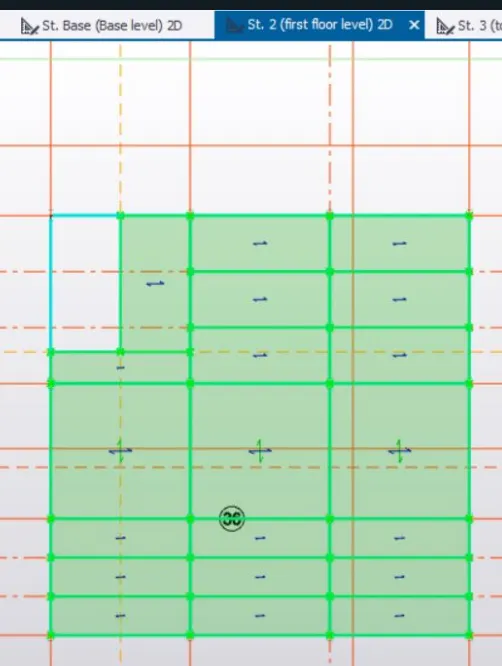
- Click on the load's icon and select the area option under that.
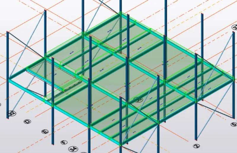
- The live loads for the structure can be obtained from the IS building standard codes.
- Now under the property dialog box enter the required load for a different room.
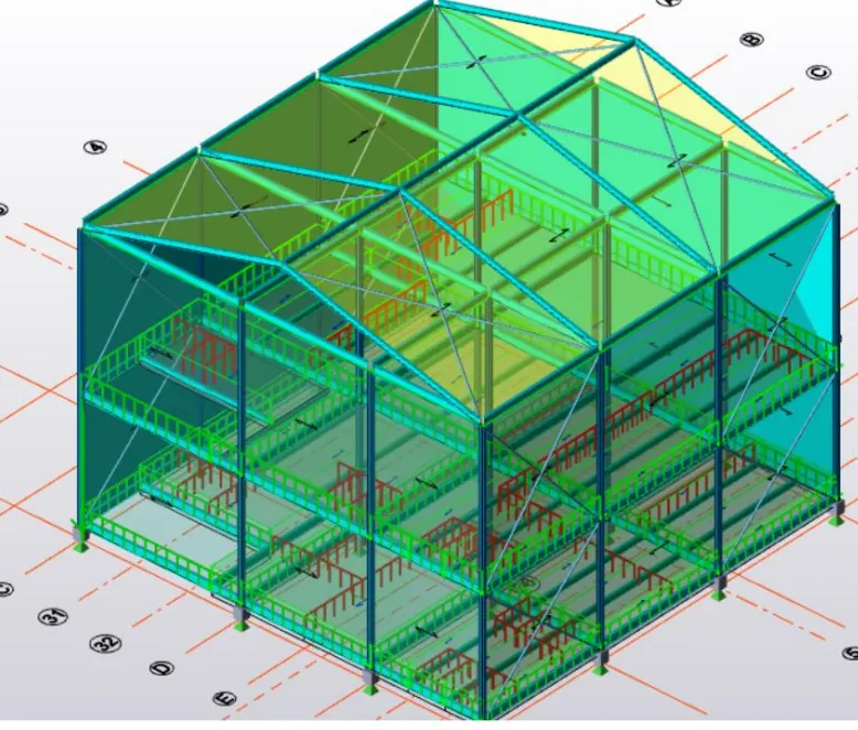
Store room = 5 KN/m^2
Office = 3 KN/m^2
Rest room = 2 KN/m^2
Toilets = 2 KN/m^2
Pantry = 3 KN/m^2
Corridor = 4 KN/m^2
Equipment room = 10 KN/m^2
- Now set the loads with different values and apply them by clicking on the respective slabs.
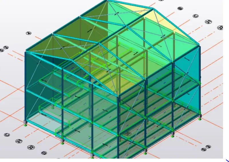
- Now repeat the same process for all the remaining levels that is for the first and to the top of the roof level.
- Do not forget to validate your model now and then to check your errors and correct them.
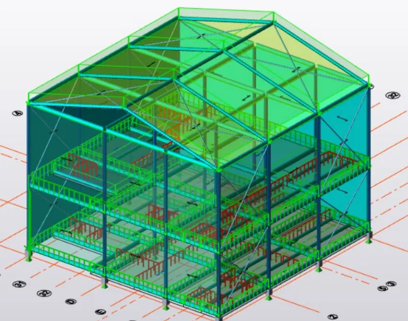
Result:
Hence by following the above procedure we can apply live loads to the structure and calculate.
_______________________________________________________________________________________________________________________________________________________
3.Generate a calculation for 5T crane loading based on the following inputs
- Centre to Centre of wheel = 10m
- Weight of crab = 40 KN
- Number of wheels = 4
- Wheelbase = 2m
Ans)
Aim: To generate a calculation for 5T crane loading based on the following inputs.
Calculation:
Max wheel load
Maximum concentrated load on crane = 50 + 10 = 60 KN.
Self-weight of crane will act as uniformly distributed load of intensity
=40 / 10 = 4 KN/m.
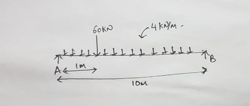
Taking moment about B :
Ra x 10 – (60 x 9)- (4 x 5 x 10) = 0
10 Ra = 740.
Ra = 74 KN.
Rb x 10 –(60 x 1)-(4 x 10 x 5) = 0
10 Rb = 260
Rb = 26 KN.
Ra + Rb = 100 KN.
The reaction from the crane girder is distributed equally on two wheels at the end of the crane girder.
Maximum wheel load on each of the crane wheel = 74 / 2 = 37KN.
MAXIMUM BENDING MOMENT :
Assume self-weight of the gantry girder as 1.5 KN/m
Total dead load = ( Self-weight of rail + self-weight of gantry girder ) 300 + 1500 = 1800 N/m
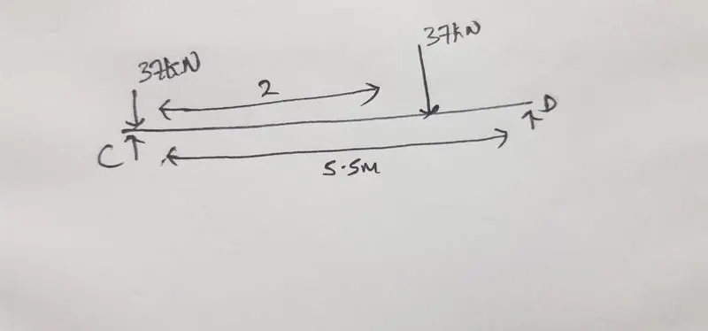
Taking moment about D
Rc x 5.5 –(37 x 4.25)- (37 x 2.25) = 0
Rc x 5.5 = 240.5
Rc = 240.5 / 5.5
Rc = 43.72 KN.
Rd x 5.5 – (37 x 1.25)- (37 x 3.25) = 0
Rd x 5.5 = 166.5
Rd = 166.5 / 5.5
Rd = 30.27 KN.
Bending moment under wheel due to live load = Rd x 2
= 30.27 x 2
= 60.54 KN.
Bending moment due to impact = 0.10 x 60.54 ( 10 % increase due to MOT)
= 6.054 KNm
Total bending moment due to live load and impact load = 60.54 + 6.054
= 66.594 KNm.
Bending moment due to dead load = W x l x l / 2
= 1.8 x 5.5 x 5.5 / 2 = 27.22 KNm
Maximum bending moment = 66.594 + 27.22
= 93.814 KNm.
MAXIMUM SHEAR FORCE :
For maximum shear force, one of
Rc x 5.5 –(37 x 5.5)-(37 x 2.5) = 0
Rc = 9.25 + 20.35 / 5.5
Rc = 5.381 KN
The maximum shear force due to wheel load = 5.31 KN
LATERAL FORCES :
Lateral forces traverse to rails = 5% of the weight of crab and weight lifted
= 0.05 ( 40 + 10 )
= 2.5
Lateral forces on each side wheel F1 = 2.5 / 2 = 1.25 KN
Maximum horizontal reaction due to the lateral force by proportion at C
= Lateral force x reaction at C due to vertical load / maximum wheel load due to vertical load
= 1.25 x ( 43.72 / 37) = 1.44 KN
At D
2.5 – 1.44 = 1.06 KN
Bending moment due to lateral load by proportion
= (1.25 / 37) x 5.31
= 0.179 KNm.
Result:
Hence by following the above steps of the procedure we could generate the calculation for the 5T crane loading.
_______________________________________________________________________________________________________________________________________________________