REVIT_Introduction to REVIT_Week 1
1 Ans)
AIM:- To create a new project (Structural / Architectural / Construction template ) and name the project appropriately.
TOOLS REQUIRED:-
- file toolbar
PROCEDURE:-
STEP-1:- to create a structural template file.
- First, open Autodesk Revit software 2021.
- Then select new command on left from models (or) select new from files option on the top left corner.
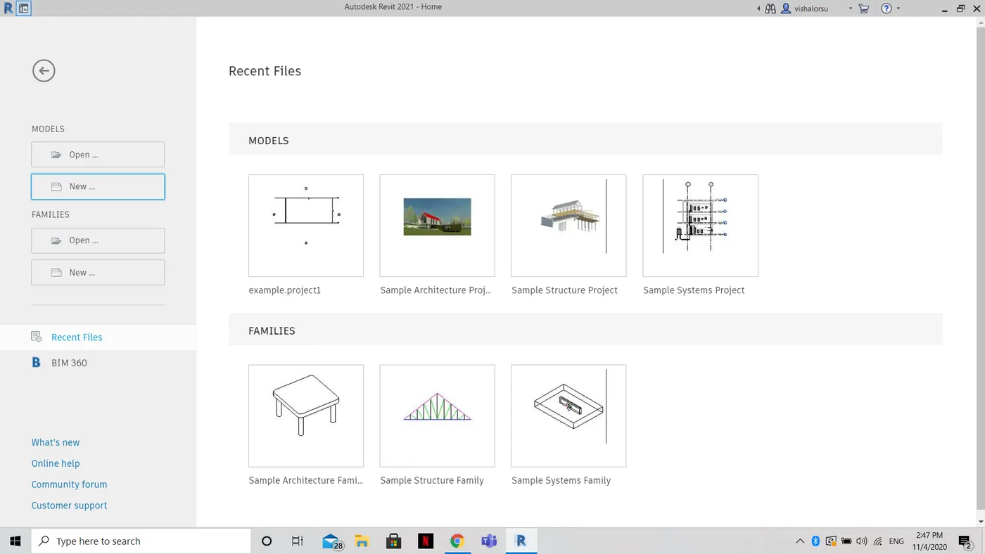
- (or)
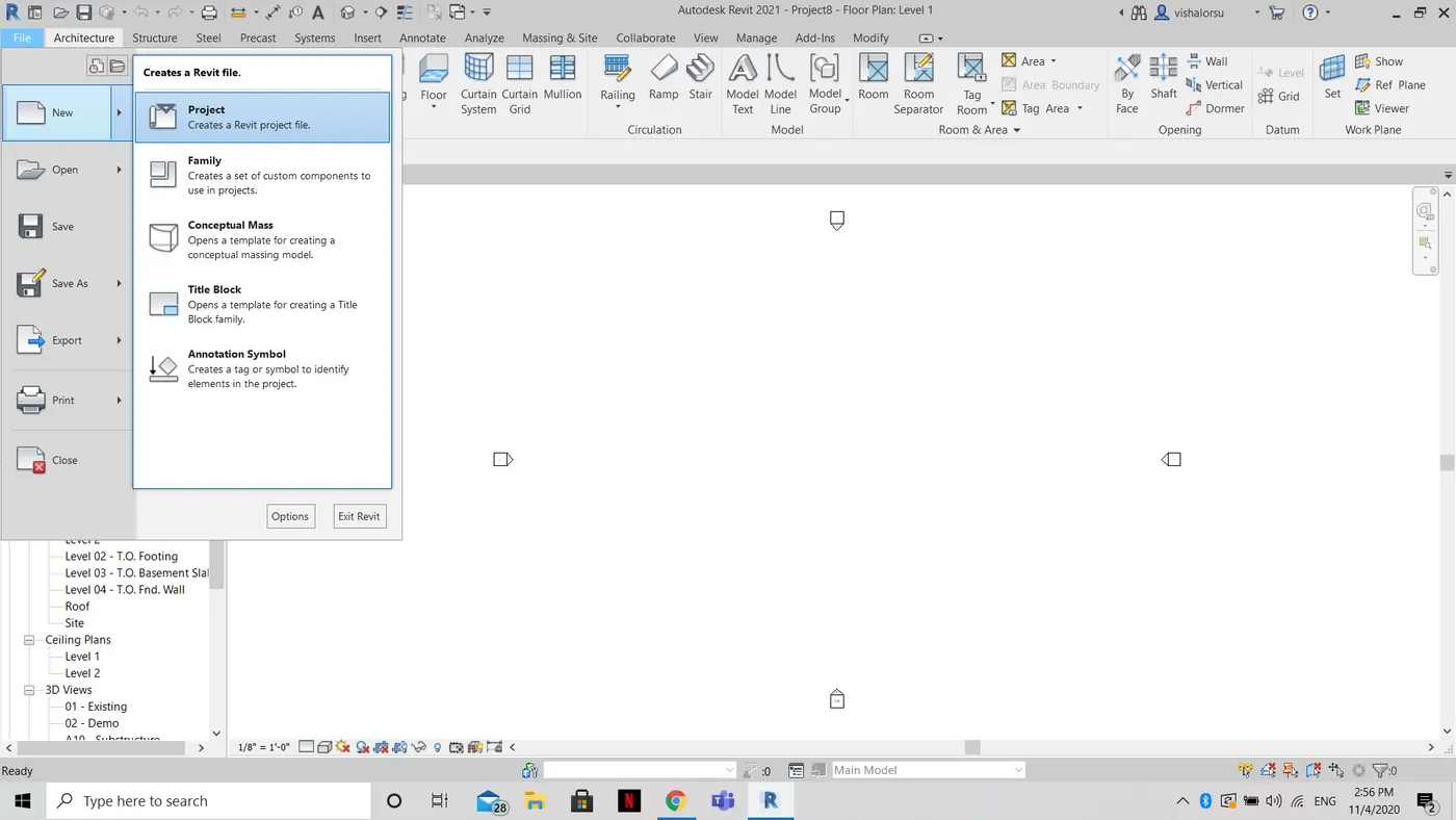
- then next choose a structural template project from the options and select ok.
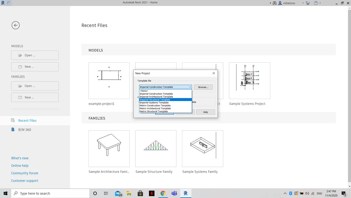
- the new project file is opened.
STEP 2:- To create a new architectural template.
- Similarly from the above steps choose the architectural template and select ok.
- A new architectural template project will be created.
STEP 3:- To create a new construction template.
- Similarly from the above steps choose the construction template and select ok.
- A new architectural template project will be created.
RESULT:- New project (Structural / Architectural / Construction template ) are successfully created.
________________________________________________________________________________________________________________________________________________________________________
2 ANS)
AIM:-
- To save the new project file.
- To close and open using icons from the file toolbar.
TOOLS REQUIRED:-
- file toolbar
PROCEDURE:-
STEP 1:- To save the new project file.
- First, open Autodesk Revit software 2021.
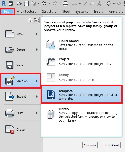
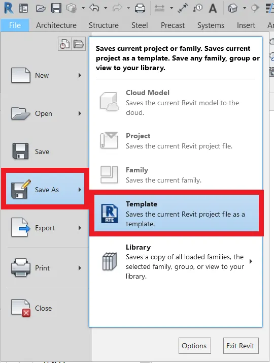
- Click File
- Go to Save As
- Choose Template
- Choose a location and name and click Save
STEP 2:- To close and open using icons from the file toolbar.
A) To open a file using icons from the file toolbar.
- First, open Autodesk Revit software 2021.
- next, click the file command on the top left corner.
- next, click the open icon and choose a file.
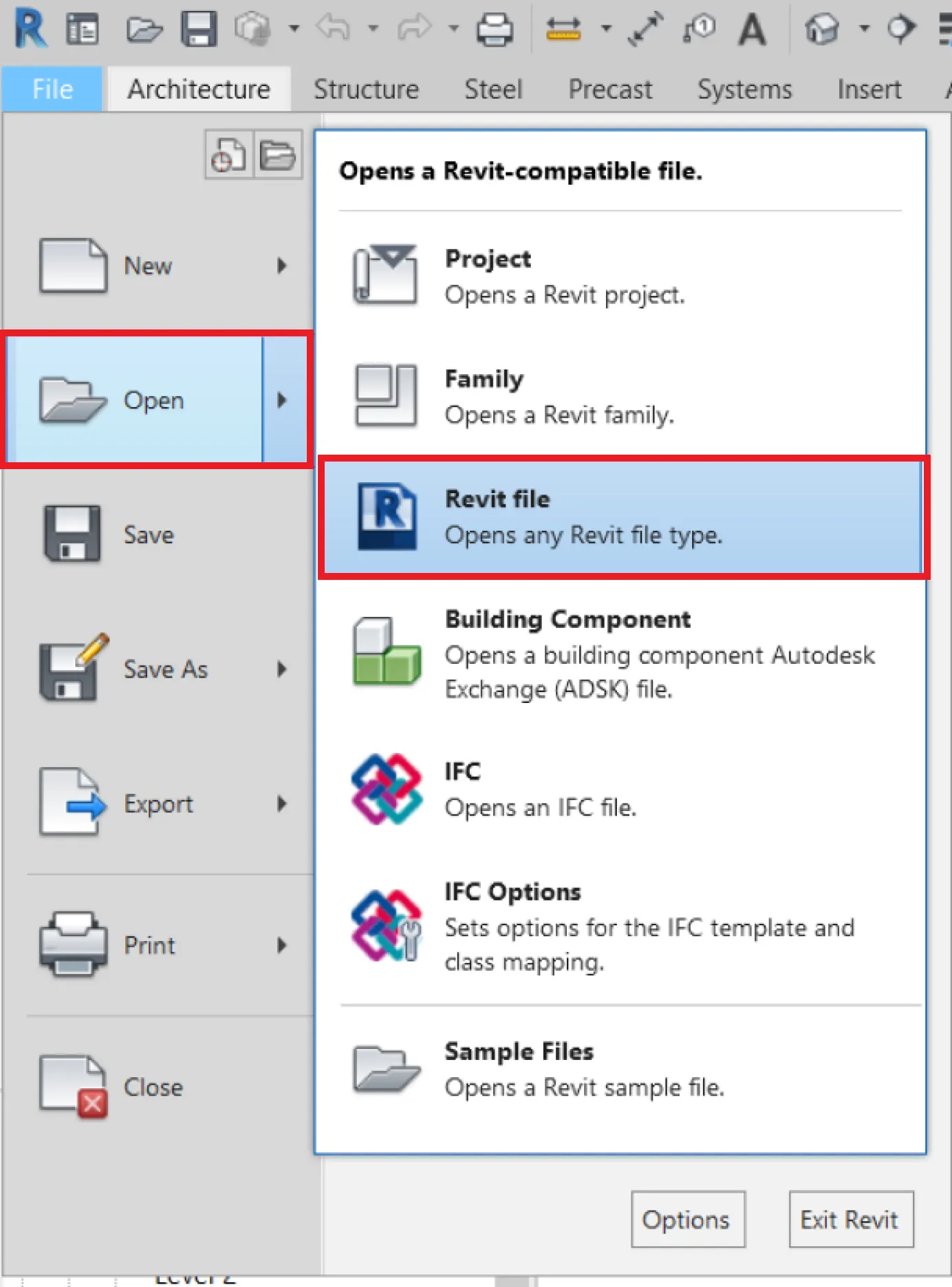
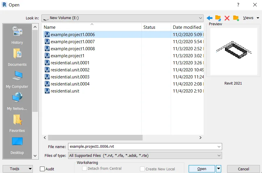
Now click open.
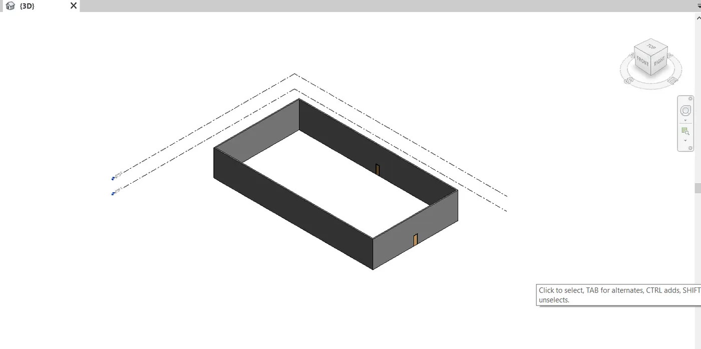
the file is opened successfully.
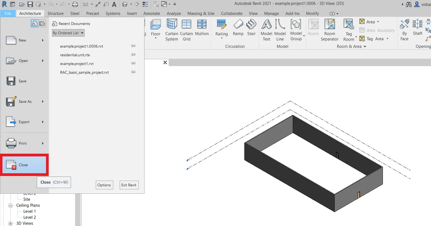
B) To close a file using icons from the toolbar.
- open the file and press the close icon as shown.
RESULT:-
- the new project file is successfully saved.
- To close and open using icons from the file toolbar is done successfully.
________________________________________________________________________________________________________________________________________________________________________
3 ANS)
AIM:-
- To draw a wall from architecture/structure toolbar and to create a rectangular layout of walls of about 40’-0” X 35’-0”.
TOOLS REQUIRED:-
- architecture or structure toolbar
- wall
- line
- rectangle
PROCEDURE:-
- First, open Autodesk Revit software 2021 and open any project template.
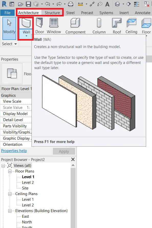
- Now choose wall command from either structure or architecture toolbar.
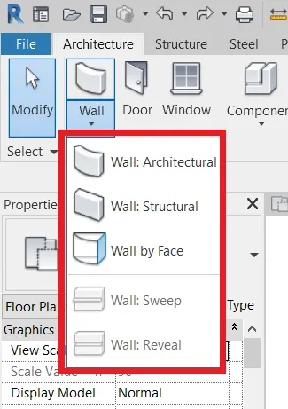
- there we have different options for walls and choose any required wall of the following.
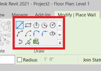
- We can use a line or in any other shape using the following polygons.
- Now using line, click and drag to draw a wall for required dimensions.
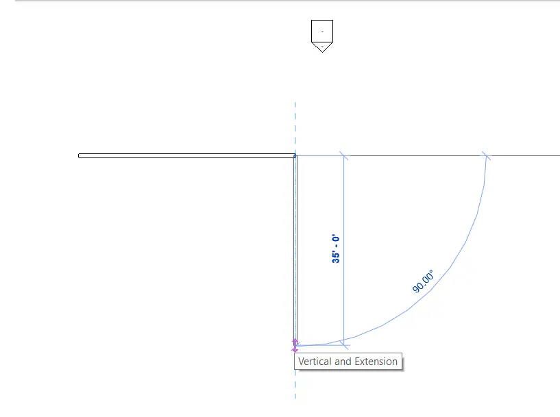
- draw a rectangular wall with dimensions 40'-0" & 35'-0"'
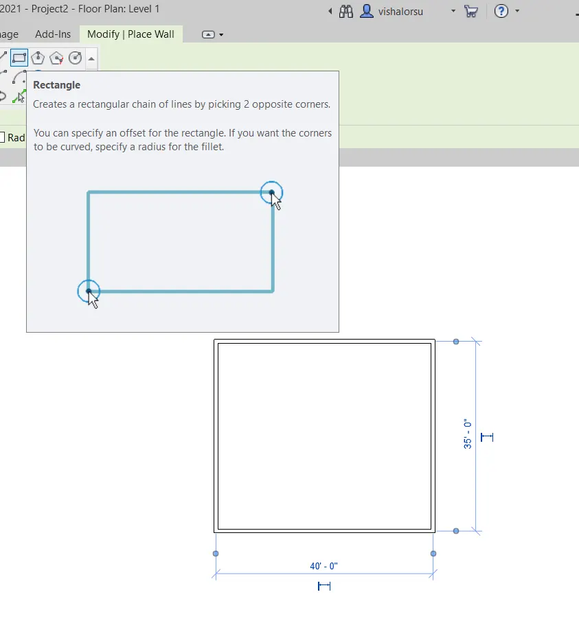
RESULT:- A rectangular layout of walls of about 40’-0” X 35’-0” is drawn successfully.
________________________________________________________________________________________________________________________________________________________________________
4 ANS)
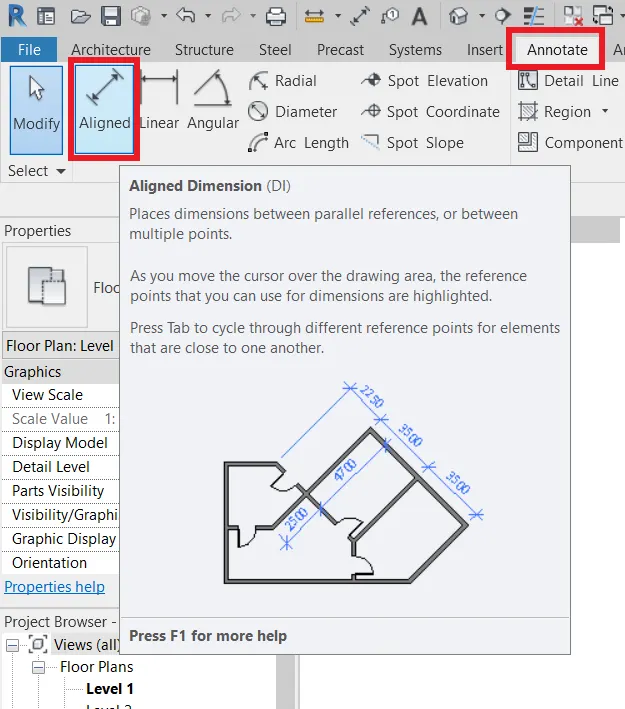
AIM:- To use an annotate toolbar and aligned option to add dimensions to the layout.
TOOLS USED:-
- Aligned dimension.
- Annotate toolbar.
PROCEDURE:-
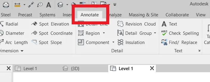
- First, use the Annotate toolbar as shown.
- Then next use aligned dimension as shown below.
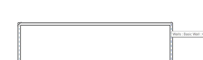
- using aligned dimension click the starting and ending points to place the dimensions as shown below.
- place the dimension horizontally and vertically as well.
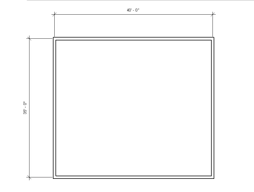
RESULT:- Aligned dimension was used successfully to place the dimensions for the rectangular layout of the wall.
________________________________________________________________________________________________________________________________________________________________________
5 ANS)
AIM:- To use the properties browser to switch to different wall types
TOOLS USED:-
- wall
- properties browser
PROCEDURE:-
- First, select or choose the walls that you want to switch to different wall types.
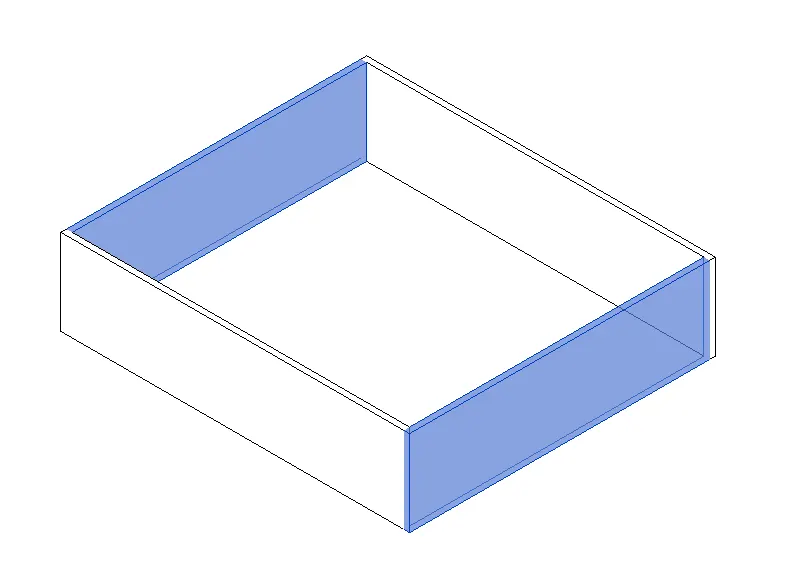
- Next, at the top left, there will be a properties bar as shown.
- click that properties bar and different types of walls appear.
- Then choose which type of wall that needs to be switched with a required one, as shown below.
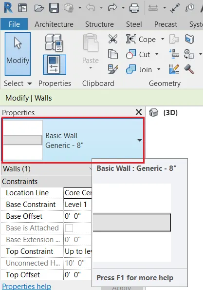
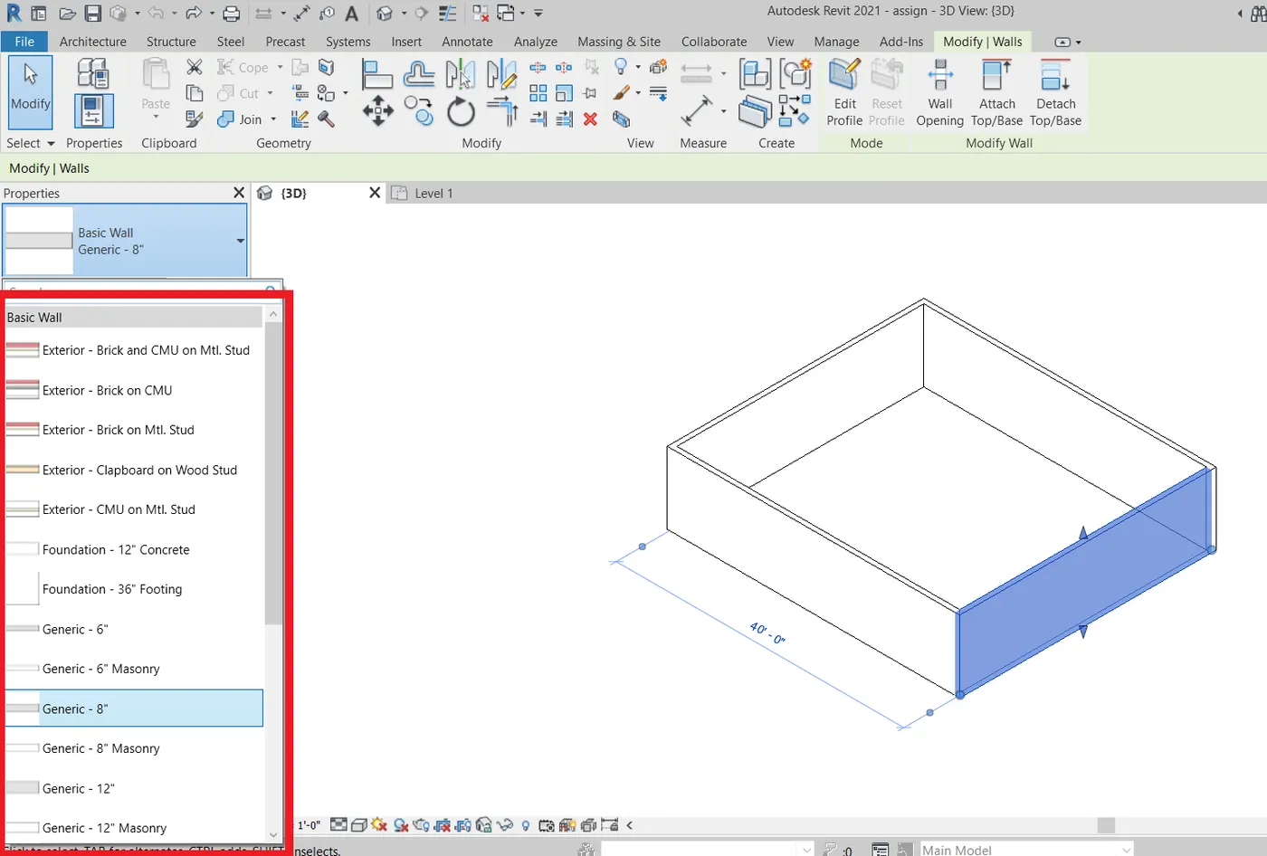
- These are the different types of walls in the properties browser existing in Revit 2021.
RESULT:- The properties browser was used to switch to different wall types.
________________________________________________________________________________________________________________________________________________________________________
6 ANS)
AIM:- To create a 3D view from the view tool bar and save the view with appropriate name.
Tools used:-
- view toolbar
- Default 3D view.
PROCEDURE:-
- First, open the view toolbar as shown.
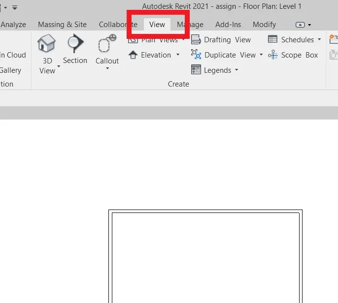
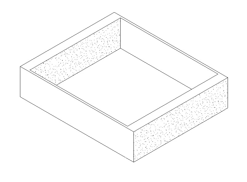
- Next, under the view toolbar click the 3D view icon as shown.
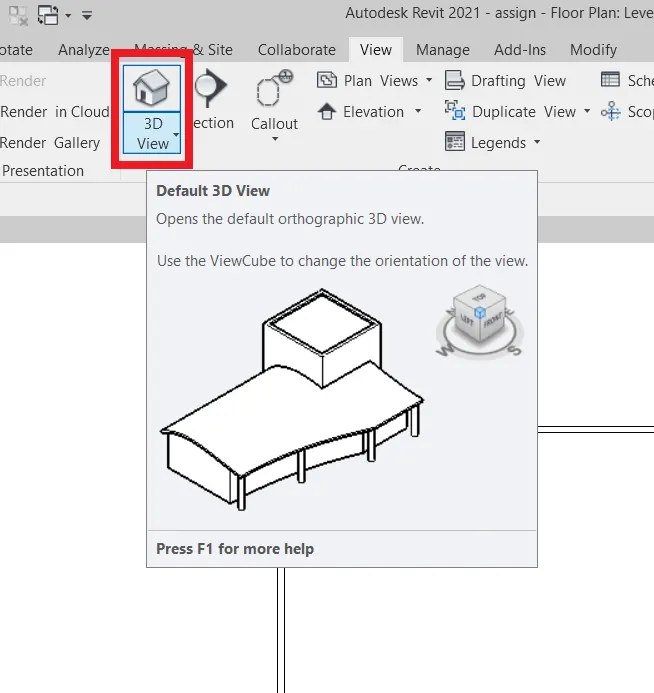
- after clicking the 3D view icon another window with a 3D view in it popped out as shown.
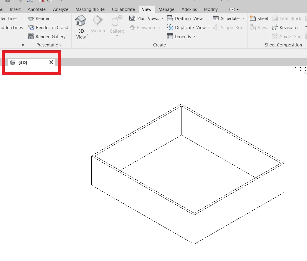
- after the 3D view is opened, now save the file as shown from the file toolbar.
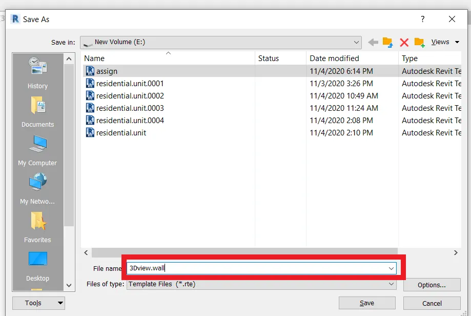
- this is how a 3D view is created.
RESULT:- 3D view from the view toolbar is created successfully and the view is saved with an appropriate name.
________________________________________________________________________________________________________________________________________________________________________
7 ANS)
AIM:- To navigate through the 3D model using view cube. Orbit/pan through the model layout created
TOOLS REQUIRED:-
- view cube
PROCEDURE:-
First after changing to a 3D model we can change the view by clicking and rotating the view cube accordingly such that to acquire the required view.
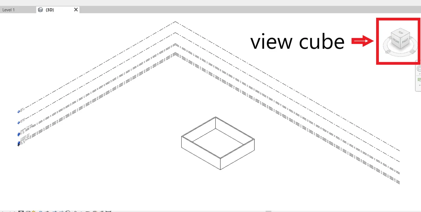

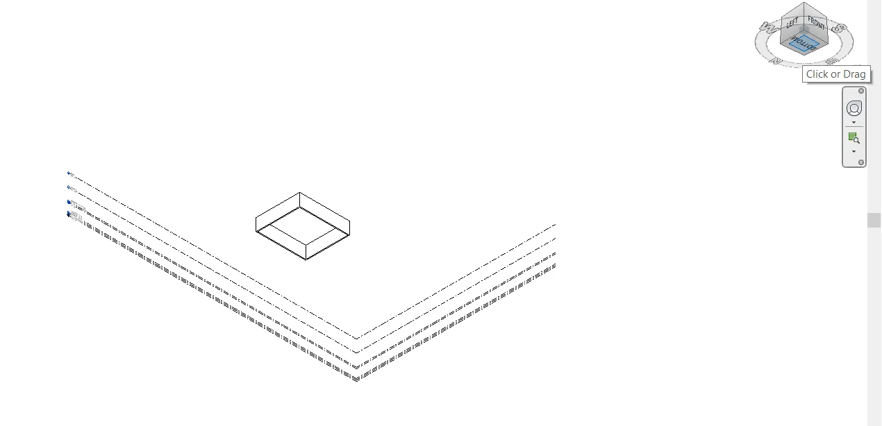
RESULT:- navigating through the 3D model using the view cube has been done successfully.
________________________________________________________________________________________________________________________________________________________________________
8 ANS)
AIM:- To switch model to shaded, realistic, hidden lines options using visibility settings
TOOLS REQUIRED:-
- visual style tool
PROCEDURE:-
STEP1:- to switch model to shaded using visual style tool as shown below.
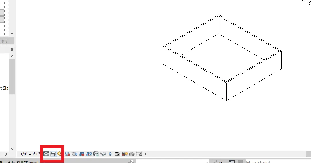
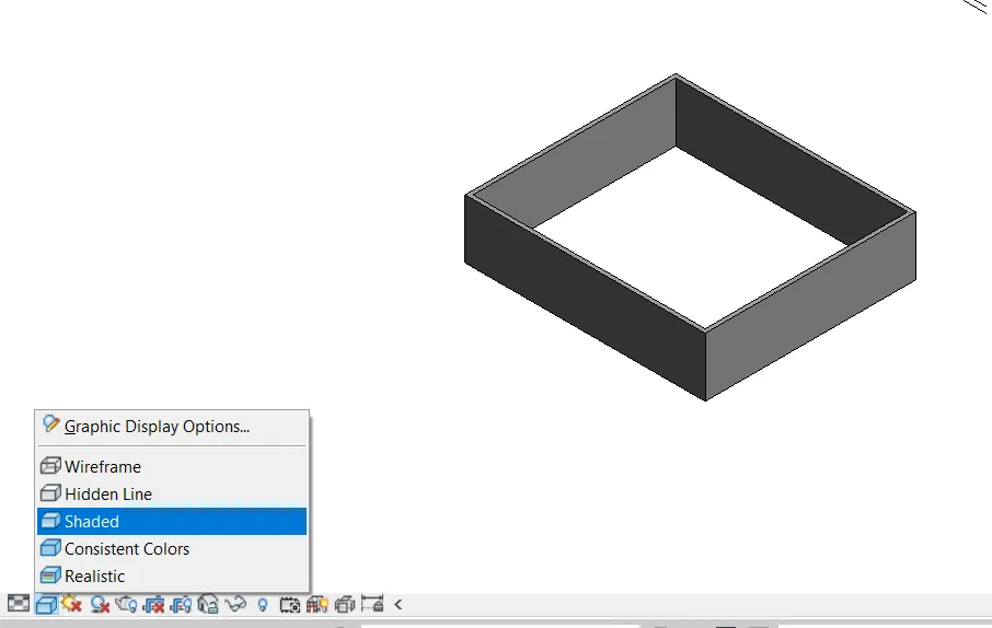
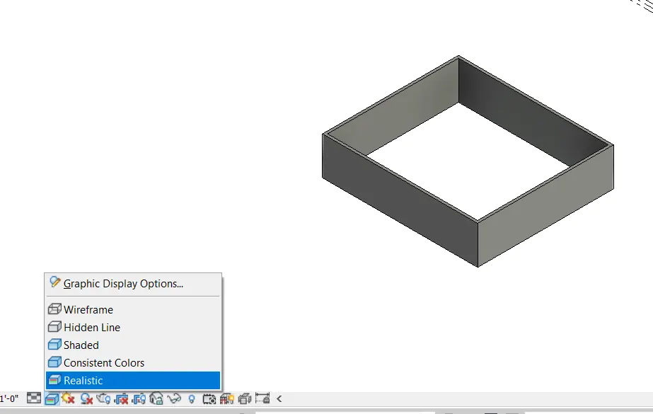
STEP 2:- to switch the model to realistic using visibility settings.
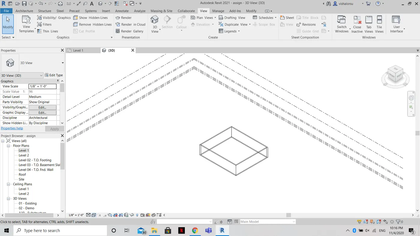
STEP 3: To switch the model to hidden lines using visibility settings.
RESULT:- switching model to shaded, realistic, hidden line options using visibility settings is done successfully.
________________________________________________________________________________________________________________________________________________________________________
9 ANS)
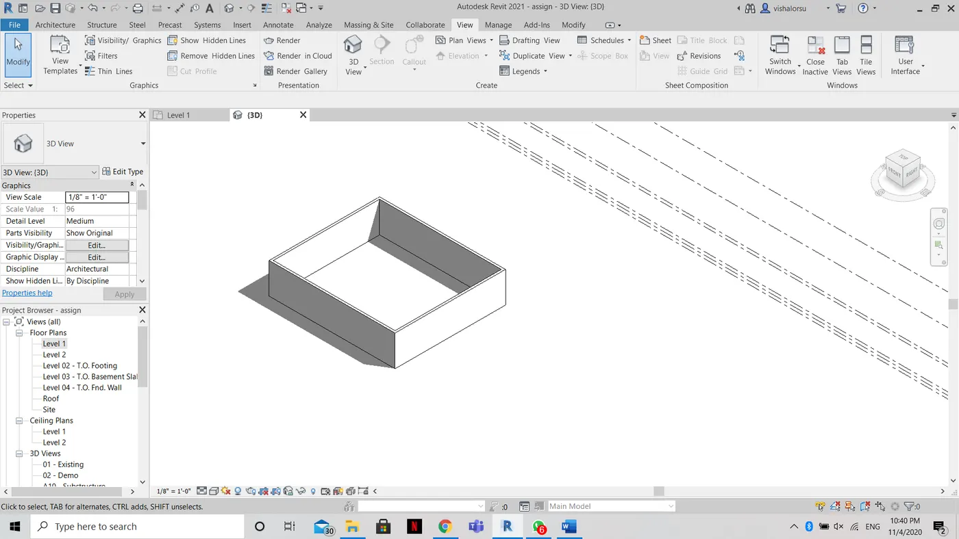
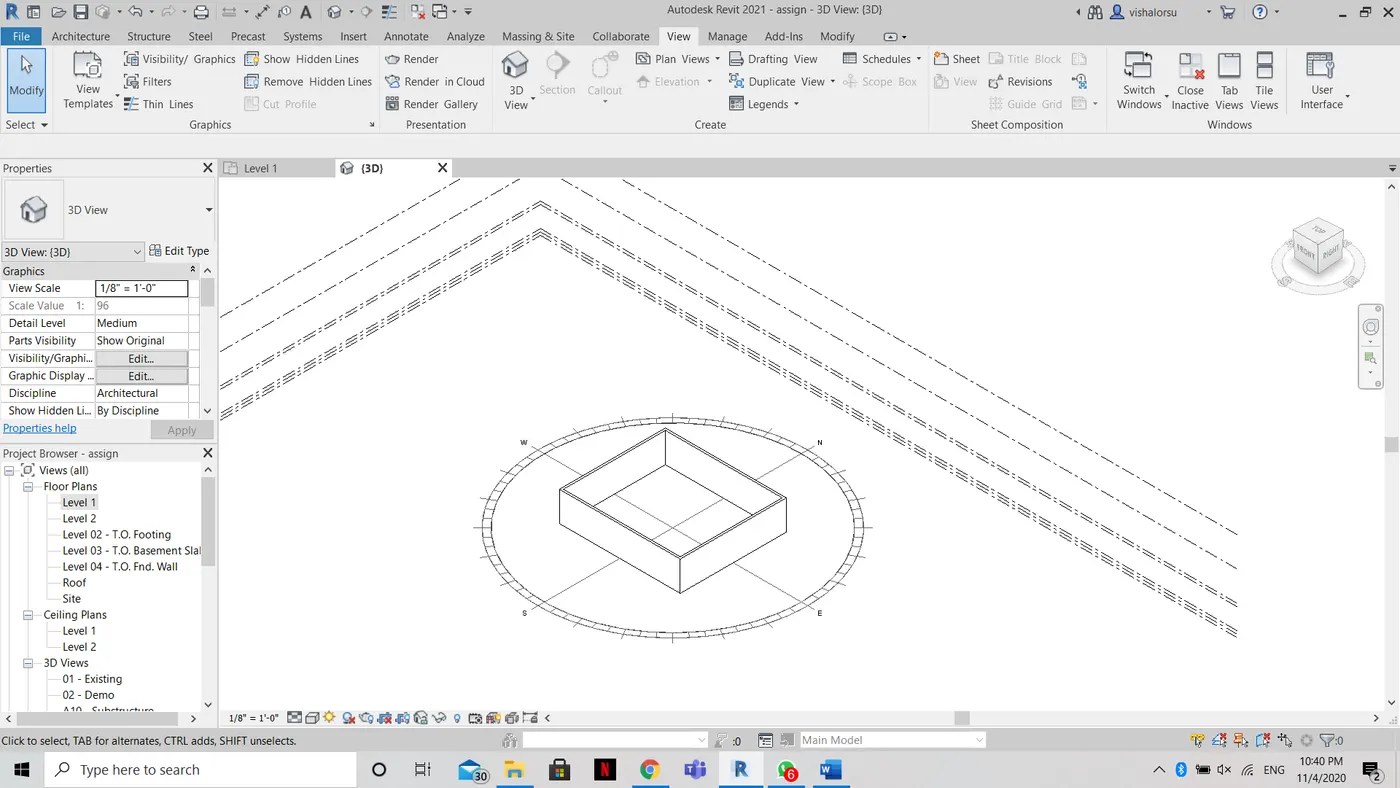
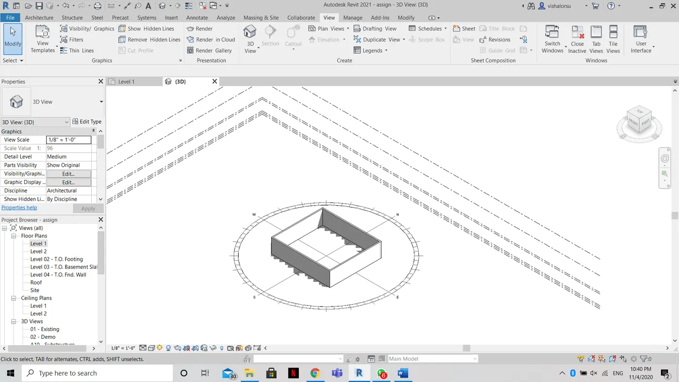
AIM:- To turn the sunlight on and off to view shadings in the layout created
TOOLS REQUIRED:-
- Sun setting tool
PROCEDURE:-
- Click on the sun setting tool which is available at the left bottom.
- There is an availability of two options, sun path on and off
- this is how sunlight is turned on and off as shown.
RESULT:-
the sunlight is turned on and off successfully to view shadings in the layout created.
________________________________________________________________________________________________________________________________________________________________________
10 ANS)
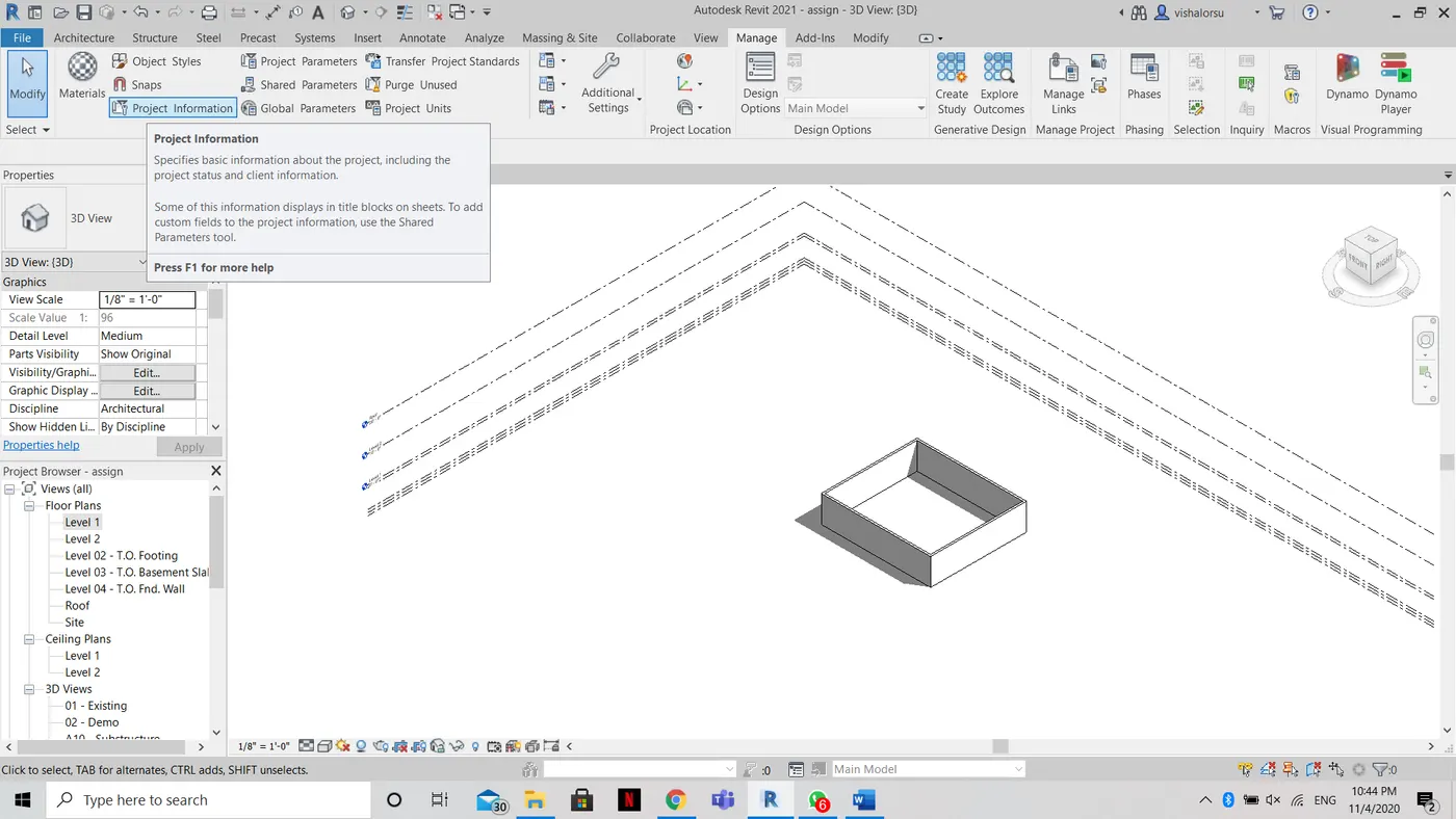
AIM:-To use the Manage tool bar to enter project settings, project name and project issue date
TOOLS REQUIRED:-
- Manage tool bar
- Project information tool
PROCEDURE:-
- First, click on the manage tool to open the manage tool bar
- Now we will find the project information icon under the setting section in manage tool bar
- By clicking the project information tool, a box is popped out and we can enter the name, issue date and we can also change the project settings
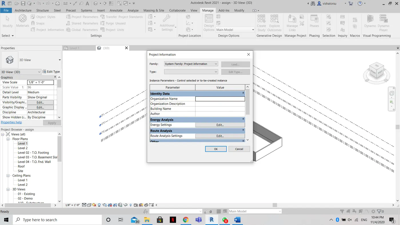
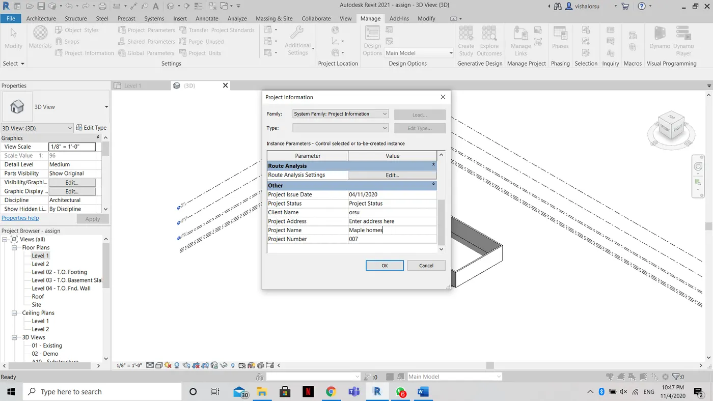
RESULT:- using the Manage toolbar to enter project settings, project name and the project issue date is done successfully.
________________________________________________________________________________________________________________________________________________________________________
11 ANS)
Analyze toolbar provides us with load combinations, boundary conditions, loads, and loads cases adjustment and support systems. we get to adjust the model and verifies the analytical and physical model for the consistency space separation, tagging and naming are also available.
________________________________________________________________________________________________________________________________________________________________________
12 ANS)
Links that support Revit to link models are
• Link Revit
• Link IFC
• Link CAD
• Link Topography
• DWF Markup
• Point Cloud
• Coordination Model
• Link PDF
• Link Image
• Manage links.
________________________________________________________________________________________________________________________________________________________________________
13 ANS)
To link up multiple revitt models together we use Collaborate Tab that is any member among a particular team can have access to do change required that is very much useful when a team consists different teams working around that is for a steel designer to a meachanical engineer . This helps people there to work with higher accuracy which will increase the efficiency .
________________________________________________________________________________________________________________________________________________________________________