Week 4 Challenge
"Tooling direction" typically refers to the strategic approach or guidance taken in the development and deployment of tools, software, or resources within an organization or project. It encompasses decisions about the types of tools to invest in, how they should be integrated into the existing workflow, and the overall objectives and goals that the tools are meant to achieve. This concept is often used in the context of software development, manufacturing, or any domain where the use of specialized tools can significantly impact efficiency, productivity, and outcomes.
In software development, for instance, tooling direction might involve decisions about which programming languages, frameworks, version control systems, testing tools, and deployment pipelines to use. It considers factors such as the project's requirements, the team's expertise, scalability needs, and long-term maintenance considerations. The tooling direction can influence the entire development lifecycle, from coding and testing to deployment and monitoring.
Ultimately, the tooling direction aims to optimize processes, streamline workflows, and enable teams to work more effectively while aligning with the overarching goals of the organization or project. It requires careful consideration, planning, and adaptation as technology and project needs evolve over time.
REPORT:
Objectives:
- Creation of Tooling Axis.
- Creation of Class B and Class C surface.
- Creating a solid part out of surface modelling.
- Draft Analysis of Class A surface and final plastic component.
Tool Used: CATIA V5
Introduction:
In this project we are designing a tail light lens using given class A surface. The approach includes creation of Class B surface keeping 4 mm thickness AND 10 degree Draft angle keeping in mind for the complete component. The design also included Class C creation from the given parent surface.
CLASS A: Following surface is given as the input for the component creation.
To continue with the design process first we need to find out the tooling axis for the surface and check for all the drafts using Draft Analysis tool of CATIA.
TOOLING DIRECTION :
Created Tooling Direction by taking point wich is centre of momentb of gravity and creadted line which is normal to surface
Draft Analysis for Surface A:
The analysis is done for 10 degree draft. So as can be seen all the surfaces are than 10deg.
Creation of Class B:
- Now for Class B creation, we have extracted surface from Class A and untrimmed them to obtain the original parent surface.
- These surfaces are then offset to the required thickness.
- After offsetting, all the surfaces are trimmed into the required shape.
- Required fillets are given to the surfaces.
Creation of Class C:
- For creating this surface we have extracted the boundry of Class A using multi-extract and then converted to smooth curve.
- Now this smooth curve is swept along the draft direction with a 3deg draft.
Class A + Class C:
To make sure that there is not any open boundry between class A and class C, we have used join option to created the single body. This is done to make sure that the parting line doesn't lie between the these two surfaces.
Class A + Class B + Class C:
For this we have trimmed the above shown surface with the Class B surface using trim feature.
All the main features are published as can be seen in the image shown above.
Draft Analysis on the Final Component:
For this analysis, main tooling axis is taken draft reference.
Following results were obtained:
TRANSPERENT VIEW OF TAIL LIGHT LENS
PARTING LINE :
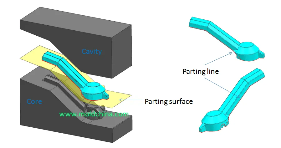
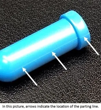
A parting line refers to the boundary line or edge where two separate pieces of a mold meet. In manufacturing, molds are used to create products through a process called injection molding. The parting line separates the two halves of the mold and determines where the mold will split to release the finished product. The quality and accuracy of the parting line are crucial for producing high-quality products with consistent dimensions. The design of the parting line can affect the appearance of the product, its functionality, and its ease of assembly. Therefore, designers and manufacturers must carefully consider the placement and design of the parting line to ensure optimal results.
PARTING SURFACE
A parting surface, also known as a parting line, is a boundary line on a molded object that separates the two halves of the mold used to create the object. The parting surface is crucial in the molding process because it helps to determine the complexity and design of the mold. The location of the parting surface is determined by the shape and geometry of the object being molded, and it must be carefully designed to ensure that the mold can be easily separated from the object without causing damage. The surface is typically smooth and flat to ensure a proper seal between the two halves of the mold, and it may require additional features such as grooves or pins to aid in the separation process.