Week 4 Challenge
TOOLING DIRECTION:
- The direction in which the mold or core and cavity opens is the tooling axis.
- Considering the Ejection from the cavity of the mould after manufacturing the interior trim must have the nominal 3-degree draft angle bit for this challange we are considering 10 degrees .
- Hence the tooling axis is created by considering the above factor.
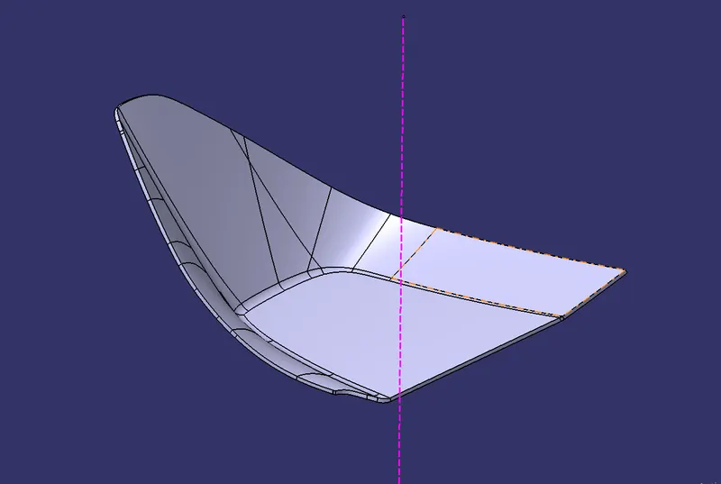
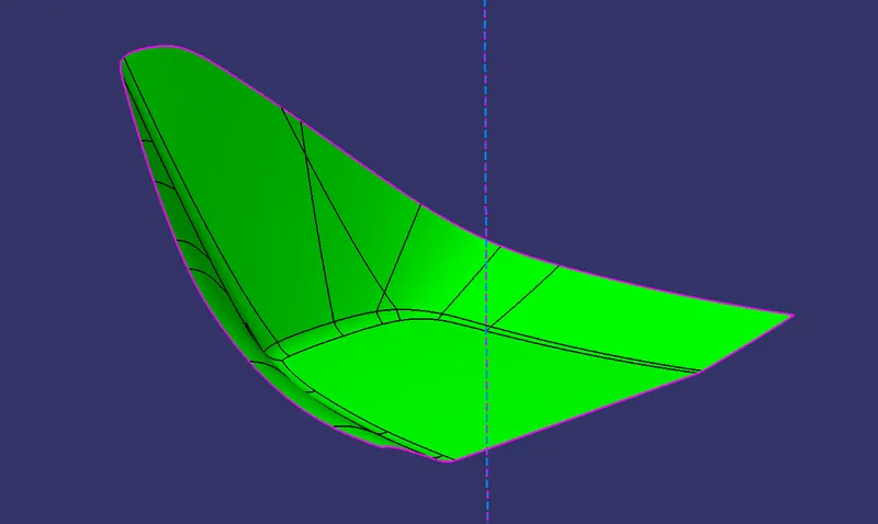
- In this case below is the tooling axis that I have used.
- The Line in the pink color is our tooling axis
DRAFT ANALYSIS :
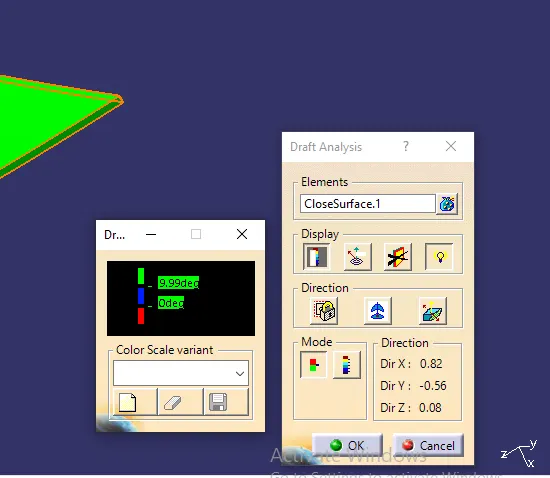
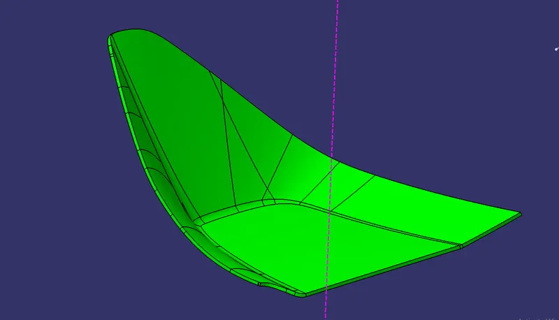
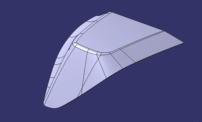
The draft analysis technique is used to analyze whether our part model created in CAD is manufacturable based on the draft condition applied. Here the part should get easily removed from the panel dies (in case of Sheet metal part) or Mold (in case of plastic).
No parts can be ejected from the tool if it is having a straight 90-degree profile from its base surface. A small draft angle is provided to each and every area of the component in order to get easy removal of the component from the tool.
Here we are providing a direction in which components should eject in order to get easy removal of components from the tool. In other words, it also lets us know whether the model is having a draft angle and how much is the draft angle from the tool direction.
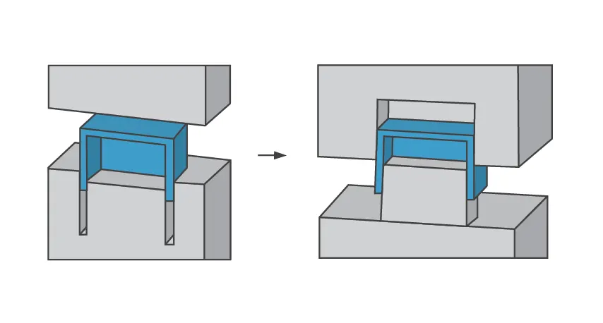
Core and Cavity Design:
The mold core and cavity are shaped sections in either half of the mold tool which give the plastic product its final shape. The hot molten material is injected into the core and cavity and then sets hard into shape. The design of the core and cavity is essential in the correct formation of the product. The sequence of events during the injection mold of a plastic part is called the injection molding cycle. The cycle begins when the mold closes, followed by the injection of the polymer into the mold cavity. A core is usually made of the best quality sand and is placed into the desired position in the mold cavity. Core prints are added to both sides of the pattern to create impressions that allow the core to be supported and held at both ends.
Parting Line:
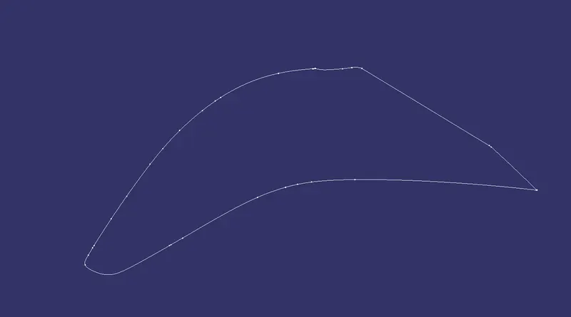
Parting line are where the two halves of the mold meet. This generally create a physical line on a part that is both visible and noticeable to the touch. These lines however can be hidden or minimized when placed along edges of the part. It is represented by WHITE line in the below picture.
Using Intersection tool in Surface Workbench we can easily get the parting Line for this model.
CLASS B SURFACE:
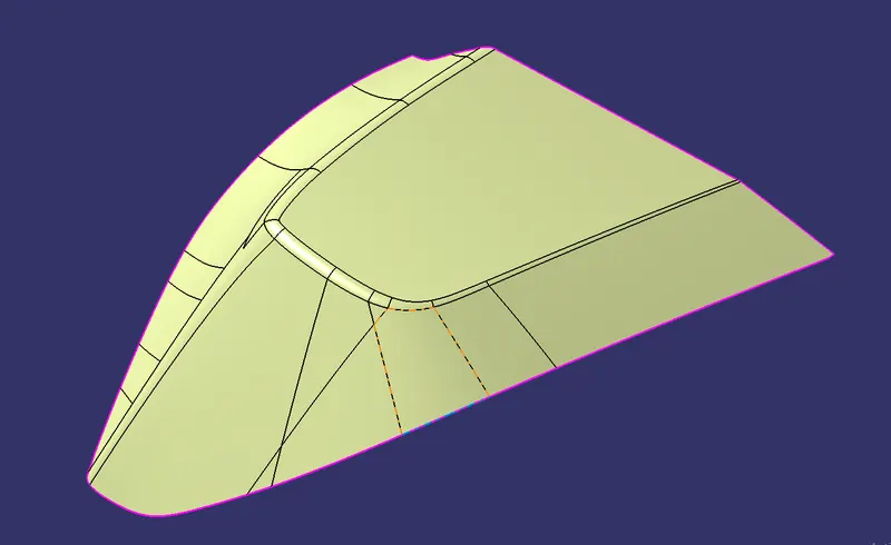
- Class B surfaces are Engineering Surfaces which are invisible to the eyes or often on the back side of the Class A surfaces.
- It is mainly the thickness of the component or Class A.
- These surfaces need to be designed as per the Class A surface i.e., the continuity, thickness of the component, functionality etc should be maintained.
- These surfaces include the main engineering features such as Screw bosses, Ribs, Snaps, Stiffeners and fixations.
- B surfaces also do not contain any aesthetic styling content and textures since it is not visible to eyes.
- Below is the image of CLASS B that I have created
CLASS C SURFACE:
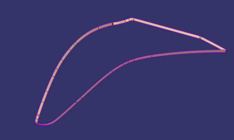
- Class C surfaces are connectors between Class A and B surfaces.
- This surface connects both A and B surfaces along the Tooling Axis.
- It contains the draft as per the design.
- It is basically the thickened surface between both A and B surface.
- Below is the Class C surface that I have created for this model
CLOSED SURFACE:
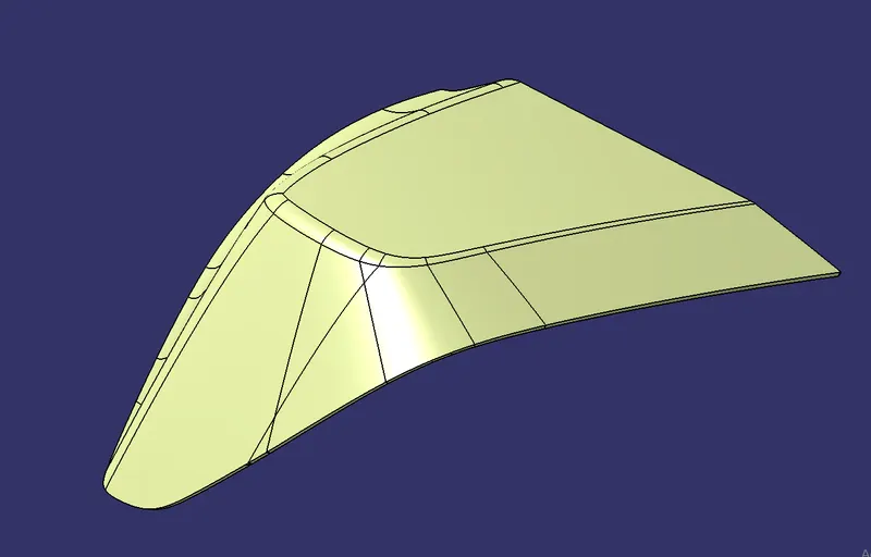
- Now the class – A and Class- C surfaces were joined together by removing the gaps in-between them with the help of extrapolation and Trim surface.
- Then, by defining the part body by using the Closed Surface command in Part Design, the component's solid body is created.
FINAL SOLID BODY:
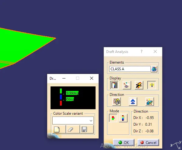
SOLID DRAFT ANALYSIS :