Week 4 Challenge
Question 1: -
Section classification problem for listed beam shapes
Calculate section classification of following beam shapes
Answer: -
Assume all Sections are Fy 250.
ε = (250/fy)1/2 = (250 / 250)1/2 = 1
ISMB 500
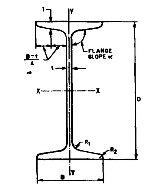
From Table,
d = 500 mm
b = 180 mm
tf = 17.2 mm
tw = 10.2 mm
As per IS 800 : 2007 Table 2
b / tf = 180 / 17.2 = 10.47 < 10.5 ε
d/tw = 500 / 10.2 = 49.02 < 84 ε
Hence it is classified as a Compact section (Class 2).
ISMC 200
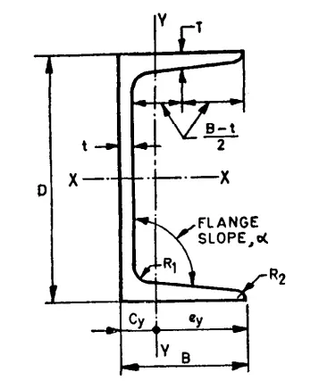
From Table,
h = 200 mm
b = 75 mm
tf = 11.4 mm
tw = 6.1 mm
As per IS 800 : 2007 Table 2
b/tf = 75 / 11.4 = 6.58 < 9.4 ε
d/tw = 200 / 6.1 = 32.79 < 84 ε
Hence it is classified as a Plastic section (Class 1).
PG 1300 x 450 x 20 x 12
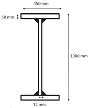
As per IS 800 : 2007 Table 2
b/tf = 450 / 20 = 22.5 < 29.3 ε
Hence it is classified as a Plastic section (Class 1).
Double angle (Back to back) – 2 x ISA 75x75x6
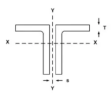
From Table,
b = 75 mm
tf = 6 mm
As per IS 800 : 2007 Table 2
b/tf = 75 / 6 = 12.5 < 15.7 ε
Hence it is classified as a Semi Compact section (Class 3).
RHS - 150 x 100 x10
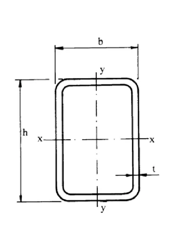
d/tw = 150 / 10 = 15 < 42 ε2
Hence it is classified as a Plastic section (Class 1).
Built-up box – 1000 x 450 x 20 x 12
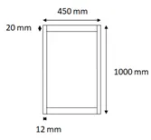
d/tw = 1000 / 12 = 83.33 < 84 ε
Hence it is classified as a Plastic section (Class 1).
Question 2: -
Effective length problems
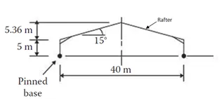
Calculate effective length of rafter made up of Built-up I section about major (x-x) and minor axis (y-y) having purlin spaced at 1.2 m.
Answer: -
Rafters are in compression which is a Continuously supported.
Length of Rafter = 5.36/Sin 15° = 20.71 m
As per IS 800 : 2007 Table 15,
Effective Length = 0.85 L
Therefore, Effective length of Rafter = 0.85 x 20.71 = 17.60 m
Question 3: -
Deflection of a beam problem
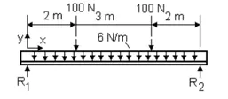
- Calculate deflection at the centre of the beam shown below. EI = 20 x 106Nm2
Given data: -
a = 2 m
b = 3 m
L = 7 m
W = 100 N
w = 6 N/m
EI = 20 x 106 Nm2
Answer: -
Deflection at Centre = WL3 /24EI x [ 3a/L – 4(a/L)3] + 5wL3 / 384EI
= 100 x 73 / (24 x 20 x 106) x [(3 x 2 / 7) – 4 x (2 / 7)3]
+ 5 x 6 x 73 / (384 x 20 x 106)
∆max(at centre) = 0.056 mm
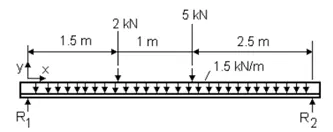
- Calculate deflection at the centre of the beam shown below. EI = 25 x 106Nm2
Answer: -
Given data: -
a = 1.5 m
b = 1 m
c = 2.5 m
L = 5 m
W1 = 2 kN
W2 = 5 kN
w = 1.5 kN/m
EI = 25 x 106 Nm2
Answer: -
Deflection at Centre = W1L3 /48EI x [ 3a/L – 4(a/L)3] + W2L3 /48EI x [ 3c/L – 4(c/L)3] + 5wL3 / 384EI
= 2000 x 53 / (48 x 25 x 106) x [(3 x 1.5 / 5) – 4 x (1.5 / 5)3]
+ 5000 x 53 / (48 x 25 x 106) x [(3 x 2.5 / 5) – 4 x (2.5 / 5)3]
+ 5 x 1500 x 53 / (384 x 25 x 106)
∆max(at centre) = 0.783 mm
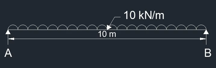
- A simply supported beam is 10 m long with udl of 10 kN/m Calculate the Flexural stiffness (EI) of the beam which limits the deflection to 5 mm at the middle.
Answer: -
Given data: -
L = 10 m
w = 10 kN/m
∆max(at centre) = 5 mm
Answer: -
∆max(at centre) = 5wL3 / 384EI
EI = 5wL3 / (384 x ∆max)
= 5 x 10000 x 103 / (384 x 5 x 10-3)
EI = 26.04 x 10⁶ N / m2
Question 4: -
Moment capacity determination problem
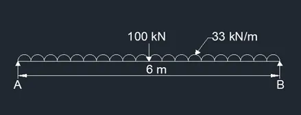
Select a standard hot rolled section for the beam which is simply supported of length 6 m spaced at 3 m c/c, carrying a floor Dead load of 5 kN/m2 (including Self weight) & Live load of 6 kN/m2 and a concentrated load of 100 kN at mid span of beam. The beam is laterally restrained and assumes bearing length of 50 mm
Tip steps:
Calculate maximum bending moment & required plastic modulus
Select suitable trial section
Calculate design shear force and design shear strength
Check design capacity of the section
Check for deflection, web buckling, bearing
Given data: -
Length = 6 m
Dead Load = 5 kN/m2
Live Load = 6 kN/m2
A Point load at midpoint = 100 kN
Bearing Length = 50 mm
Answer: -
Step 1: -
Load Calculation:
DL = 5 x 3 = 15 kN/m
LL = 6 x 3 = 18 kN/m
Total UDL = 33 kN/m
Point load at the center of span = 100 kN
Step 2: -
Shear Force:
RA + RB = 33 x 6 + 100 = 298
RA = RB
Taking moment about A
RB x 6 = 100 x 3 + 33 x 6 x 3
RB = 149 kN
RA = 149 kN
SF at A = 149 kN
SF at C (Centre) = 50 kN
SF at B = -149 kN
Hence Maximum Shear force = 149 kN
Step 3: -
Bending Moment:
MA = 149 x 6 – 100 x 3 – 33 x 6 x 3 = 0
MC = 149 x 3 - 33 x 3 x 1.5 = 298.5 kN m
MB = 0
Factored Moment = 1.5 x 298.5 = 447.75 kN m
Step 4: -
Section Modulus:
ZP (required) = M x γmo / fy = 447.75 x 106 x 1.1 / 250 = 1970.1 cm3
Choosing Section ISWB 600 @ 133.7 kg/m, Section properties from IS 808 : 1989 Table 2.2.
Shape Factor = Zp / Ze = 1.14
So, Ze (required) = 1970.1 / 1.14 = 1728.16 cm3
ZP (provided) = 4035.6 cm3 > ZP (required) = 1970.1 cm3
Ze (provided) = 3540 cm3
r1 = 17
h = 600 mm
bf = 250 mm
tf = 21.3 mm
tw = 11.2 mm
Ixx = 106198 cm4
Iyy = 4700 cm4
rxx = 250 mm
ryy = 52.5 mm
d = h – 2(r1 + tf) = 600 – 2 x (17 + 21.3) = 523.4 mm
Step 5: -
Classification of section:
As per IS 800 : 2007 Table 2
(bf / 2) / tf = (250 / 2) / 21.3 = 5.86 < 9.4
d / tw = 523.4 / 11.2 = 46.73 < 84
Hence the section is Plastic.
Step 6: -
Calculation of Shear Capacity of section:
Vd = (Av x fy) / (√3 x γmo) = (600 x 11.2 x 250) / (√3 x 1.1) = 881797 N
Vd = 881.797 kN > 1.5 x 149 = 223.5 kN
Hence Safe in Shear.
0.6 Vd =0.6 x 881.797 = 529.08 kN > V = 223.5 kN
Hence Low shear.
Step 7: -
Calculation of Design Capacity of Moment – By Interpolation method
Design Strength for laterally unsupported beam
kL / ry = 6000 / 52.5 = 114.28
hf / tf = (600 – 21.3) / 21.3 = 27.16
fcr,b IS 800 : 2007 from table 14
fcr,b = 240 N / mm2
λLT = √(fy / fcr) = √(250 / 240) = 1.02
ɸLT = 0.5 [1 + αLT (λLT - 0.2) + λ2LT]
= 0.5 [1 + 0.21 (1.02 - 0.2) + 1.022]
= 1.1063
XLT = 1 / [ɸLT + (ɸ2LT - λ2LT)0.5 ≤ 1.0
= 1 / [1.1063 + (1.10632 – 1.022)
= 0.652 < 1
Hence OK.
fbd = XLT x fy / γmo
= 0.652 x 250 / 1.1 = 148.18 N / mm2
Md = βb x Zp x fbd
= 1.0 x 4035.6 x 1000 x 148.18
Md = 598 kN m > M (447.75 kN m)
Hence Section is safe in bending stress.
Step 8: -
Check for deflection:
δ = [5wl4 / 384EI] + [Wl3/48EI]
= [ 5 x 18 x 60004 / 384] + [100 x 60003 / 48] x 1 / (20 x 104 x 106198 x 104)
δ = 1.43 + 21.18 = 22.61 mm
Permissible maximum deflection as per IS 800 Table 6 for Live load with Elastic cladding
= L / 240 = 6000 / 240 = 25 mm > 22.61 mm
Hence safe in deflection.
Step 9: -
Check for Web Buckling:
d / tw = 523.4 / 11.2 = 46.73 < 67ε
Hence OK
So no need to check for web buckiling.
Step 10: -
Check for Web Crippling
n1 = 2.5 x (tf + r1) = 2.5(21.3 + 17) = 95.75 mm
As per IS 800 : 2007 Clause 8.7.4
Fw = [(b1 + n2) x tw x fy)] / γmo
Where b1 = Length of stiff bearing = 50 mm
n2 = Length of load dispersion
= [(50 + 95.75) x 11.2 x 250] / 1.1
= 371000 N = 371 kN > V = 223.5 kN
Hence safe in Bearing
Result: -
- Thus, it is concluded that the beam ISWB 600 @ 133.7 kg/m, is capable to resist bending moment of 548.70 kN m safely.
Question 5: -
Purlin design problem
Design channel purlin, considering sag rod at mid span for the roof truss having following data
Span of truss : 20 m
Spacing of Truss : 4 m c/c
Roof slope : 20 degrees
Spacing of purlin : 2 m
Wind suction : 1 kN/m2
Live Load : 0.75 kN/m2
Dead Load 1.4 kN/m2
Given data: -
Span of truss = 20 m
Spacing of Truss = 4 m c/c
Roof slope = 20 degrees
Spacing of purlin = 2 m
Wind suction = 1 kN/m2
Live Load = 0.75 kN/m2
Dead Load = 1.4 kN/m2
Answer: -
Step 1: -
Calculation of Load:
Dead Load perpendicular to the rafter = 1.4 Cos 20°
= 1.4 x 0.939 = 1.3146 kN/m2
Dead Load per meter (Load/m2 x spacing of purlin) = 1.3146 x 2 = 2.6292 kN/m
Live load perpendicular to the rafter = 0.75 Cos 20°
= 0.75 x 0.939 = 0.7042 kN/m2
Live Load per meter (Load/m2 x spacing of purlin) = 0.7042 x 2 = 1.4084 kN/m
Wind Load perpendicular to the rafter = 1.0 Cos 0°
= 1.0 kN/m2
Wind Load per meter (Load/m2 x spacing of purlin) = 1.0 x 2 = 2.0 kN/m
Load Combination (1) = 1.5 x (DL + LL)
= 1.5 x (2.6292 + 1.408)
= 6.0558 kN/m
Load Combination (2) = 1.5 x (DL + LL – WL)
= 1.5 x (2.6292 + 1.408 – 2.0)
Worst Load combination = 6.0558 kN/m
Dead load parallel to the rafter = 1.4 Sin 20°
= 1.4 x 0.342
= 0.4788 kN/m2
Dead Load per meter(Load/m2 x spacing of purlin) = 0.4788 x 2 = 0.9576 KN/m
Live load parallel to the rafter = 0.75 Sin 20°
= 0.75 x 0.342 = 0.2565 kN/m2
Live Load per meter (Load/m2 x spacing of purlin) = 0.2565 x 2 = 0.513 kN/m
Wind load parallel to rafter = 0.00
1.5 x (DL+LL ) = 1.5 x (0.9576 +0.513) = 2.2059 kN/m
Step 2: -
Bending moment calculation:
BM about Z-Z Mz = wl2 / 10 = 6.0558 x 42 / 10 = 9.689 kN m
(Purlin is continuous over PR of Truss)
BM about Y-Y My = wl2 / 10 = 2.2059 x 42 / 10 = 3.529 kN m
Step 3: -
Calculation of Shear Force:
Fz = wl/2 = 6.0558 x 4 / 2 = 12.117 kN
Fy = wl/2 = 2.2059 x 4 / 2 = 4.419 kN
Step 4: -
Selection of Trial Channel section for purlin:
ISMC 200 selected for purlin
Properties taken from Steel Tables
h = 200 mm
bf = 75 mm
tf = 11.4 mm
tw = 6.1 mm
h1 = 150.2 mm
Izz = 1819.3 mm4
Zpz = Mz x γmo / fy + (2.5 D / bf ) My x γmo / fy
= 9.689 x 106 x 1.1 / 250 + (2.5 x 200 / 75) x 3.529 x 106 x 1.1 / 250
= 42631.6 + 6.6666 x 15527.6 = 146147 mm3
X – Coordinate C.G of the channel section
200 x 6.1 + 2 x 11.4 X = 2 x (68.9 – X) x 11.4
X = 7.69 mm
Zpy = (600 x 6.1) (6.1/2 + 7.69) + 2[(68.9 x 11.4) (68.9/2 – 7.69)]
= 39308.4 + 42037.819
= 81346.2 mm3
Step 5: -
Section Classification:
d / tw = 150.2 / 6.1 = 24.62 < 42 ε
ε = 1
b / tf = 75 / 11.4 = 6.57 < 9.4 ε
Hence the section is Plastic.
Step 6: -
Calculation of Shear Capacity of section:
About Z axis
Vd = (Av x fy) / (√3 x γmo) = (200 x 6.1 x 250) / (√3 x 1.1) = 160.083 kN
0.6 Vd =0.6 x 160.08 = 96.05 kN > Fz = 12.117 kN
Hence Safe.
About Y axis
Vd = (Av x fy) / (√3 x γmo) = (2 x 75 x 11.4 x 250) / (√3 x 1.1) = 224.38 kN
0.6 Vd =0.6 x 224.38 = 134.628 kN > Fy = 4.419 kN
Hence Safe.
Design Moment in Z direction
Mdz = βb x Zpz x fy / γmo
= 1.0 x 146147 x 250 / 1.1 = 33215227.3 N mm
Mdz = 33.215 kN m > Mz (9.689 kN m)
Hence Section is safe in moment in Z direction.
Design Moment in Y direction
Mdy = βb x Zpy x fy / γmo
= 1.0 x 81346.2 x 250 / 1.1 = 18487772 N mm
Mdy = 18.48 kN m > My (3.529 kN m)
Hence Section is safe in moment in Y direction.
Step 7: -
Overall Strength condition:
Mz / Mdz + My / Mdy ≤ 1
9.689 / 33.215 + 3.529 / 18.48 = 0.292 + 0.191 = 0.483 < 1
Hence safe.
Step 8: -
Check for deflection:
Actual deflection = 5wl4 / 384EI = (5 x 1.4084 x 40004) / (384 x 20 x 104 x 1819.3 x 103) = 12.89 mm.
Permissible maximum deflection as per IS 800 : 2007 Table 6 for Live load with Elastic cladding = L / 240 = 4000 / 240 = 16.66 mm.
Actual deflection is lesser than Permissible deflection.
Hence safe in deflection.
Result: -
- It is concluded that for purlin of truss ISMC 200 section is safe in shear, moment, strength and deflection.