Week 4 Challenge
- Define tooling direction
Ans -
Explaining the Draft Analysis and the Tooling Axis creation.
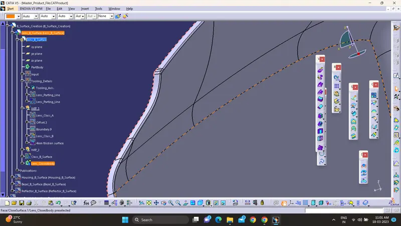
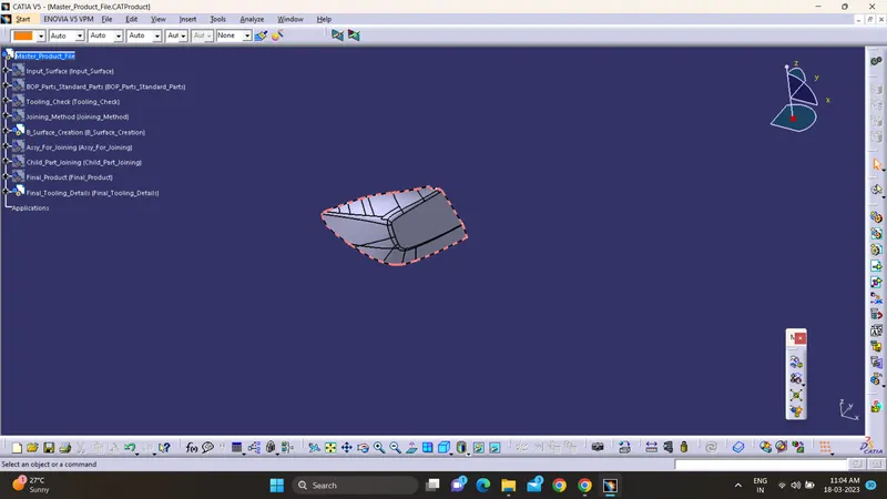
after that we need to perform Draft Analysis on CLOSED PART BODY and for that we need to attach Axis System to TOOLING AXIS after that we need to see the our surface having what Draft angle actually general draft angle ranges from 0.5 degree to 3 degree then we can see two colors on after draft anaysis it is of GREEN and Bottom of BLUE which represents that our Draft analysis is right and if we can see some RED patches on itr then our draft angle needs to be update or change then we need to check suitable draft value for it and need to Rectify that
Explaining the Draft Analysis and the Tooling Axis creation.
after that we need to perform Draft Analysis on CLOSED PART BODY and for that we need to attach Axis System to TOOLING AXIS after that we need to see the our surface having what Draft angle actually general draft angle ranges from 0.5 degree to 3 degree then we can see two colors on after draft anaysis it is of GREEN and Bottom of BLUE which represents that our Draft analysis is right and if we can see some RED patches on itr then our draft angle needs to be update or change then we need to check suitable draft value for it and need to Rectify that
Draft Analysis:-
The draft analysis will help you quickly gather the draft angle on multiple surfaces manual measurements.The first step is to change your shading style to “Shading with Material”.The next step is to click on the draft analysis icon in the Analysis toolbar.Draft analysis initially assumes a Z axis direction.This can be done with the dragging of the compass with respect to the Tool axis direction.Now that the draft direction is fixed, you can gather the draft angles along different surfaces using the “on the fly” mode. Simply activate the icon within the draft analysis dialogue box and hover your mouse over the surface.using “invert draft direction method” check the color variation in the part and analyze the draft angles in the part.now ok with this position and lock the current orientation.
DRAFT ANALYSIS OF A SURFACE:
Draft analysis of the surface is carried to check if the surface or part can be manufactured with the required draft angle.
Draft angle is needed for the component to clear the core and cavity surface as it would have shrunk towards the center while cooling.
The draft angle in this design is 10 degrees. As A surface is a single surface there won't be much difference in color. The draft analysis of A-surface is shown below.
(3)Write the definition of the Parting line
Ans -
A parting line is an inevitable part of injection molded products. It is the line of separation between where two halves of a mold meet. It manifests itself on injection molded parts as a line that runs the entire perimeter of the part. In most parts, it is just a line that runs straight down the middle. However, in more complex parts, its location varies.
While a parting line might seem harmless, it is very important in determining the usefulness of a part. This is because its position is influential in helping designers and molders to decide where to insert other features of the part. If a machinist places an important feature on the wrong side of the parting line, it could lead to serious issues with the whole injection molding process.
(4) Create B surface of the given lens in surface modeling (not in part), with a 4 mm thickness
Ans 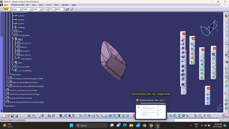
(5) Create a Parting Line for thickened lens and create a report for how you approached the parting Line and did a draft analysis?
Ans -
we took boundry of class A surface for creating parting line and from there we created parting line