Week 4- Challenge
Objective Create 1D elements on the following components with given cross-section and DOF
To create 1D cross-section elements on given component following is the procedure
Meshing Of Component
- Imported the model Imported the model using Import geometry (As shown in photograph 1)
Photograph 1
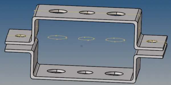
- Created Midsurface on each bracket
- By selecting upper bracket created midsurface and renamed it as bracket 1.(Assign colour for same)
- Selected lower bracket and created midsurface and renamed it as bracket 2. (Assign colour for same)
- Midsurface :- (Auto-midsurface+auto extraction+select required surface+extract) refer Photograph 2
- Using Delete command deleted the all solid elements
- Deleted the initial components of the bracket before midsurfacing
Photograph 2 (Midsurface)

- Mesh the component using automesh
- created washer splits on brackets
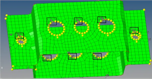
- Using automesh created meshing on brackets as shown in Photograph 3
- Selected all surface
- Element size :- 8
- Mesh type:- mixed - For proper meshing at washer split we can increase nodes by left click and decrease by right click as shown in Photograph 4
Photograph 3 (Automesh)

Photograph 4
Create cross section using HYPER-BEAM command
- Using hyperbeam command following cross-sections are created:-
i ) Rod element:-
Cross-Section: BOX- Dimension a= 12 mm
dimension b=10 mm
Thickness t= 0.75 m
ii) Beam element:-
Cross-Section: I Section- Dimension a= 8 mm
Dimension b= 10 mm
Dimension c= 8.5 mm
Thickness t1= 0.75 mm
Thickness t2= .6 mm
Thickness t3= .6 mm
iii) Bar element:-
Cross-section: C section- Dimension DIM1= 5 mm
Thickness DIM2= 1.2 mm
Dimension DIM3= 10 mm
Thickness DIM4= 1.2mm
Assign Material & properties
1) Assign material
- Right click on Tabbar- create- select Material
- Renamed it as steel and assigned properties to that material
-card image - assign MAT1 as a random (we can change it according to solver / material)
-we can also assign density, young modulus etc
2) Assign properties
I) For Bracket
- Right click on Tabbar- create- select property
- Renamed it as bracket 1 and assigned properties to that bracket1
- Card image PSHELL (In optistruct if mesh is using midesurface then card image must be PShell)
- Assigned material as steel
- we can also assign thickness etc - similarly properties are created and renamed it as bracket 2
- Created properties are assign to components accordingly.
II) For Rod Bar and beam
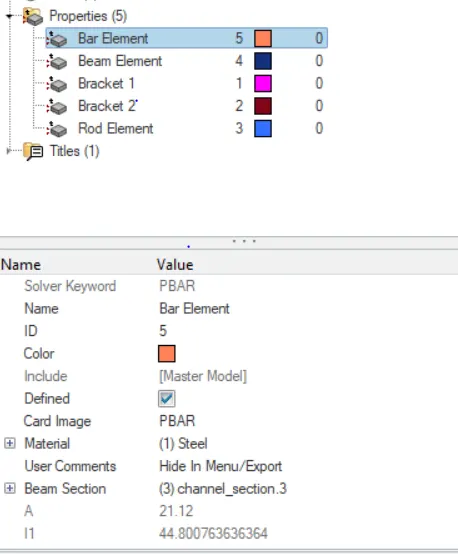
- Card image for rod, bar & beam are PRod, PBar & PBeam
- Selected material as steel
- selected beam section accordingly
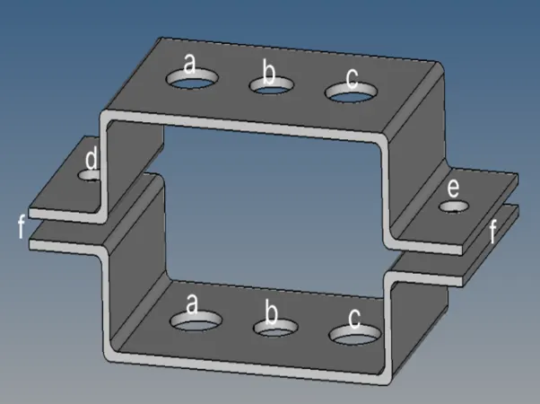
Photograph 5
Rod element
- created RBE2 element using rigid command. (at a-a photograph 5)
Photograph 6 (RBE2 Element)
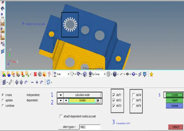
- Rod command is used to create rod element by selecting the nodes
- Assign properties to rod element using update option refer photograph 7
photograph 7

Beam element
- created RBE3 element using rbe3 command. (at b-b photograph 5)
- Using bars command created a beam element as shown in photograph 8
- also updated property as bar element
photograph 8

Bar element
- created RBE3 element used rbe3 command. (at c-c photograph 5)
- Using bars command created a beam element as shown in photograph 9
- also updated property as bar element
photograph 9

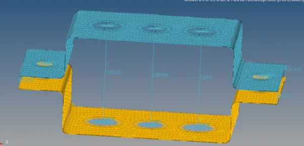
photograph 10 (Spring element, rod element, bar element)
Create Mass
- create RBE2 link using rigid command (at d & e photograph 5)
- using mass command, by selecting the nodes (mass =10) created a mass refer photograph 11
photograph 11

Spring element
- by selecting the nodes spring elements are created at edges refer photograph 10 and photograph 12
photograph 12

photograph 13 (Final model Image)
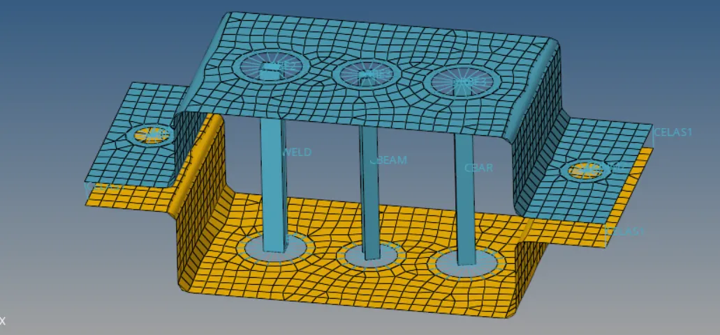
Results:- Using midurfacing successfully created a 1D elements on the components with given cross-section.