Week 4 Challenge
1) AIM : To classify the sections based on the given shapes.
INTRODUCTION : ISMB500, ISMC200, PG 1300*450*20*12, 2ISA 75*75*6, RHS 150*100*10, Builtup 1000*450*20*12 are the sections to be classified.
PROCEDURE :
a) ISMB 500
Flange
Width of flange = 180 mm. So b = 90 mm.
Thickness of flange tf = 17.2 mm.
b/tf = 5.232 < 9.4. Since ε = 1. Hence flange is plastic.
Web
depth of web d = D - 2*tf = 500-(2*17.2) = 465.6 mm
Thickness of web tw= 10.2 mm
Neutral axis is at mid depth
d/tw = 45.64 < 84. Hence web is plastic.
Since both flanges and web of ISMB 500 are plastic, whole section is plastic.
b) ISMC 200
Flange
Width of flange b = 75 mm.
Thickness of flange tf = 11.4 mm.
b/tf = 6.58 < 9.4. Since ε = 1. Hence flange is plastic.
Web
depth of web d = D - 2*tf = 200-(2*11.4) = 177.2 mm
Thickness of web tw= 6.1 mm
Neutral axis is at mid depth
d/tw = 29.05 < 42. Hence web is plastic.
Since both flanges and web of ISMC 200 are plastic, whole section is plastic.
c) PG 1300 x 450 x 20 x 12 (Considering welded section)
Flange
Width of flange = 450 mm. So b = 225 mm.
Thickness of flange tf = 20 mm.
b/tf = 11.25 < 13.6 Since ε = 1. Hence flange is semi-cpmpact.
Web
depth of web d = D - 2*tf = 1300-(2*20) = 1260 mm
Thickness of web tw= 12 mm
Neutral axis is at mid depth
d/tw = 105. Hence web is compact.
Since flange is semi-compact and web is compact, the section is semi-compact.
d) 2 ISA 75*75*6
b = 75 mm, d = 75 mm, t = 6 mm
b/t = 12.5 < 15.7
d/t = 12.5 < 15.7
(b+d)/t = 25
Hence section is semi compact.
e) RHS 150*100*10
b = 80, d = 130 and tf b= 10
b/tf = 8 < 29.3
d/tf = 13 < 29.3
Hence section is plastic.
f) Builtup box – 1000 x 450 x 20 x 12
b = 426, d = 960, tf = 20, t = 12
b/tf = 21.3 < 84
d/t = 80 < 84.
Hence section is plastic.
RESULT :
a) ISMB 500 - Plastic section.
b) ISMC 200 - Plastic section.
c) PG 1300 x 450 x 20 x 12 - Semi Compact Section.
d) 2 ISA 75*75*6 - Semi Compact Section.
e) RHS 150*100*10 - Plastic Section.
f) Builtup box 1000 x 450 x 20 x 12 - Plastic Section.
2) AIM : To find out the effective length of rafter about major axis(x-x) and minor axis(y-y).
INTRODUCTION : Spacing of purlins = 1.2m
Arrangement of rafter
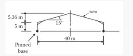
PROCEDURE :
From the above figure cos 15deg = 20/hypotenuse ⇒ hypotenuse = 20.7m
Effective length in minor axis Ly = Spacing of purlins = 1.2m.
Effective length in major axis Lx = 0.8*2*hypotenuse = 0.8*2*20.7 = 33.12m (approximately)
Exact effective length will be in between 33.12m to 40m.
RESULT :
Effective length in minor axis Ly = 1.2m.
Effective length in major axis Lx = 33.12m (approximately)
3) AIM : To find deflection for the first two beams and flexural stiffness for the third beam.
INTRODUCTION : Given beams are solved using superposition method.
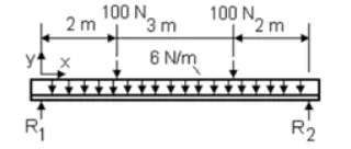
EI = 20*10^6 Nm2.
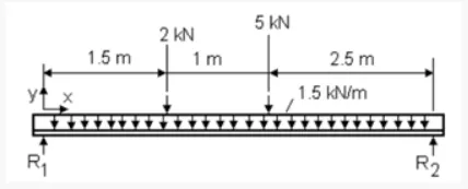
EI = 25*10^6
PROCEDURE :
a)
Length of beam L = 7m.
EI = 20*10^6 Nm2.
Deflection at centre due to udl = `(5*W*L^3)/(384*EI)`
W = 6*7 = 42N.
Deflection due to udl = 9.38*10^-3 mm.
Deflection at centre due to concentrated load at 2m from left = `(W*L^3)/(48*EI)*(3(a/L)-4(a/L)^3)`
W = 100N
Deflection at centre due to concentrated load = 0.028 mm
Deflection at centre due to concentrated load at 2m from left = `(W*L^3)/(48*EI)*(3(a/L)-4(a/L)^3)`
W = 100N
Deflection at centre due to concentrated load = 0.025 mm
Total deflection = 9.38*10^-3 + 0.028 + 0.025 = 0.062 mm.
b)
Length of beam L = 5m.
EI = 25*10^6 Nm2.
Deflection at centre due to udl = `(5*W*L^3)/(384*EI)`
W = 1.5*5 = 7.5 KN.
Deflection due to udl = 0.49 mm.
Deflection at centre due to concentrated load at 1.5m from left = `(W*L^3)/(48*EI)*(3(a/L)-4(a/L)^3)`
W = 2KN
Deflection at centre due to concentrated load = 0.17 mm
Deflection at centre due to concentrated load of 5 KN = (W*L^3)/(48*EI)
W = 5KN
Deflection at centre due to concentrated load = 0.52 mm
Total deflection = 0.49 + 0.17 + 0.52 = 1.18 mm
c) Length of simply supported beam = 10m.
UDL on simply supported beam = 10KN/m.
Deflection at centre of beam = 5mm. --- (1)
Defection at centre = (5W*L^3)/(384EI) --- (2)
From (1) and (2), EI = 260.42*10^6 Nm2.
RESULT :
a) Total defelction for beam 1 = 0.062mm.
b) Total deflection for beam 2 = 1.18mm.
c) Flexural Stiffness (EI) = 260.42*10^6 Nm2.
4) AIM : To design the laterally restrained beam for given loading conditions which is simply supported.
INTRODUCTION :
Span of simply supported beam = 6m
Spacing of simply supported beams = 3m c/c.
Floor Dead Load = 5kN/m2.
Floor Live Load = 6 kN/m2.
Concentrated load at mid span = 100kN
Bearing length = 50 mm.
PROCEDURE :
Step 1 : Loads acting on beam
UDL acting on the beam due to dead load D.L = 5*3 = 15 KN/m
UDL acting on the beam due to live load L.L = 6*3 = 18 KN/m
Concentrated Load at mid span = 100KN
Factored Concentrated Load = 1.5*100 = 150KN
Factored U.D.L = 1.5(15+18) = 49.5 KN/m
Step 2: Shear Force and Bending moments of beam
Total load due to concentrated load = 150KN
Total Load due to UDL = 49.5*6 = 297KN
Total Load acting on the beam = 150+297 = 447KN
S.F at ends of the beam Max S.F= 447/2 = 223.5KN
Max B.M acts at centre of beam
Max B.M = (223.5*3)-(49.5*3*1.5) = 447.75KNm
Step 3: Selection of suitable section
Required Plastic Section Modulus Zp = (Max B.M)/(fy/γmo) = (447.75*10^6)/(250/1.1) = 1970.1 *10^3 mm3.
Select suitable section from SP6
Properties of Section
Zpz = 2228.16*10^3 mm3.
Zez = 1933.2*10^3 mm3.
Overall depth of section D = 550 mm.
Width of flange bf = 190 mm.
Thickness of the web tw = 9.9 mm.
Thickness of flange tf = 15mm.
Root Radius R = 18 mm.
d = D - 2(tf+R) = 550 - 2(15+18) = 484mm.
Izz = 53161.6*10^4 mm4.
(bf/2)/tf = (190/2)/15 = 6.33 < 9.4
d/tw = 484/9.9 = 48.9 < 84
Hence section is plastic.
Step 4 : Check for Shear
Vd = (fy/(sqrt(3)*γmo))*D*tw = `(250/(sqrt(3)*1.1))*550*9.9` = 714.47 KN
0.6Vd = 0.6*714.47 = 428.68 KN > V = 223.5 KN
Hence Low shear
Step 5 : Check for bending
`Md = Zp*(fy/γmo) = 2228.16*10^3 * (250/1.1)` = 506.4 KNm.
Md = 506.4KNm < `(1.5*Ze*fy)/(γmo)` = `(1.5*1933.2*10^3*250)/1.1` = 659 KN.
Md = 506.4KNm > Max B.M = 447.75 KN
Hence safe in bending
Step 6 : Check for deflection
For deflection, consider unfactored loads
Concentrated load at mid span of beam = 100KN
D.L = 15KN/m, LL = 18KN/m
Total UDL acting on the beam = DL+LL = 15+18 = 33KN/m
Maximum deflection acts at centre of beam
Deflection at centre due concentrated load = (W*L^3)/(48*EI) = (100*10^3*6000^3)/(48*2*10^5*53161.6*10^4) = 4.23 mm
Deflection at centre due to UDL = (5*W*L^3)/(384*EI) = (5*33*6*10^3*6000^3)/(384*2*10^5*53161.6*10^4) = 5.24 mm
Total deflection at centre = 4.23 mm + 5.24 mm = 9.47 mm
Allowable deflection = span/300 = 6000/300 = 20mm > 9.47mm. Hence safe
Hence safe in deflection
Step 7 : Check for web buckling
S.F is maximum at supports.
Given bearing length b = 50 mm
n1 = D/2 = 550/2 = 275 mm
Effective length of web le = 0.7*d = 0.7*484 = 338.8 mm.
Moment of Inertia I = (b*tw^3)/12 = (50*9.9^3)/12 = 4042.91 mm4.
Area A = 50*9.9 = 495 mm2.
rmin = sqrt(I/A) = sqrt(4042.91/495) = 2.86 mm
Slenderness ratio = leff/rmin = 338.8/2.86 = 119
fy = 250
Buckling class c
fcd = 84.8 N/mm2
Buckling strength of web at supports Fwb = (b+n1)*tw*fcd = (50+275)*9.9*84.8 = 272.84 KN > Max S.F at support = 223.5 KN.
Hence safe in Web buckling
Step 8 : Check for web crippling
Bearing length b = 50 mm
n2 = 2.5(tf + R) = 2.5(15+18) = 82.5
Web crippling strength = (b+n2)*tw*fy/γmo = (50+82.5)*9.9*250/1.1 = 298.13KN > Max S.F at support = 223.5 KN.
Hence safe in web crippling
RESULT :
ISLB 550 section is checked for shear, bending, deflection, Web buckling and Web crippling and proved that the member is safe for given loading.
5) AIM : To design purlin based on given load conditions.
INTRODUCTION :
Span of truss = 20m
Spacing of truss L = 4m
Roof slope = Angle between wind load and gravity loads θ = 20 degrees
Spacing of purlin = Influence length of purlins = 2m
Wind Load = 1 KN/m2
Dead Load = 1.4 KN/m2
Live Load = 0.75 KN/m2
PROCEDURE :
Step 1 : Calculation of loads acting on z-axis and y-axis
U.D.L due to wind load H = 1*2 = 2KN/m
U.D.L due to gravity loads P = (1.4+0.75)*2 = 4.3 KN/m
Unfacored Load acting along z-axis H' = P*sinθ = 4.3*sin20deg = 1.47 KN/m
Unfactored Load acting along y-axis P' = H+P*cosθ = 2+4.3*cos20deg = 6.04 KN/m
Facored Load acting along z-axis H' = 1.5*P*sinθ = 1.5*4.3*sin20deg = 2.2 KN/m
Factored Load acting along y-axis P' = 1.5(H+P*cosθ) = 1.5(2+4.3*cos20deg) = 9.06 KN/m
Step 2 : Factored S.F and B.M acting on z-axis and y-axis
Factored bending moments
Since one sag rod is used the moments are reduced by 75 percent
Mz = 0.25*P'*L^2/10 & My = 0.25*H'*L^2/10
Mz = 0.25*9.06*4^2/10 & My = 0.25*2.2*4^2/10
Mz = 3.62 KNm & My = 0.88 KNm
Factored Shear forces along z-axis and y-axis
Max S.F at ends Fy = H'*L/2 = 2.2*4/2 = 4.4KN
Max S.F at ends Fz = P'*L/2 = 9.06*4/2 = 18.12KN
Step 3 : Selection of channel section
Zpz = (Mz*γm0/fy) + 2.5d/b(My*γm0/fy) ; where d and b are depth and width of trail sections
Zpy = (My*γm0/fy) + 2.5d/b(Mz*γm0/fy)
Assume d/b = 2
Zpz rquired = (3.62*1.1*10^6/250)+2.5*2*(0.88*1.1*10^6/250) = 35288 mm3.
Assume ISMC 150
Properties of section
A = 20.88 cm2
depth D = 150mm
width b = 75mm
thickness of flange tf = 9mm
thickness of web tw = 5.4mm
Root radius r = 9.5mm
depth of web d = 150-2(9+9.5) = 113mm
Elastic Section moduli
Zez = 103.9*10^3 mm3, Zey = 19.5*10^3 mm3.
Plastic Section moduli
Zpz = 119.82*10^3 mm3, Zpy = 26.39*10^3 mm3.
Section classification
b/tf = 75/9 = 8.33 < 9.4
d/tw = 113/5.4 = 20.93 < 42
So, the section is plastic
Step 4 : Check shear capacity
Shear Capacity in z-direction(major axis)
Fdz = (fy/γm0*sqrt(3))*h*tw = (250/1.1*sqrt(3))*150*5.4 = 106.284 KN > Fz = 18.12 KN
Shear Capacity in y-direction(minor axis)
Fyz = (fy/γm0*sqrt(3))*(2*b)*tf = (250/1.1*sqrt(3))*(2*75)*9 = 177 KN > Fy = 4.4 KN
Step 5 : Check bending capacity
Mdz = Zpz*fy/γm0 < 1.2*Zez*fy/γm0
= (119.82*10^3*250)/(1.1*10^6) < (1.2*103.9*10^3*250)/(1.1*10^6)
= 27.23 KNm < 28.33 Knm . Hence okay
Mdy = Zpy*fy/γm0 < γf*Zez*fy/γm0
= (26.39*10^3*250)/(1.1*10^6) < (1.5*19.5*10^3*250)/(1.1*10^6)
= 5.99 KNm < 6.64 Knm. Hence okay
Step 6 : Check Interaction equation
(Mz/Mdz)+(My/Mdy) = (3.62/27.23) + (0.88/5.99) = 0.28 < 1 . Hence safe
Step 7 : Check for deflection
Live load = 0.75KN/m2
Wind Load = 1KN/m2
Spacing of purlins = 2m
Live load w1 = 0.75*2*cos20deg= 1.4 KN/m (normal to purlin)
Wind Load w2 = 1*2 = 2KN/m
Deflection due to live load = (5/384)*(w1*l^4/EI) = (5/384)*(1.4*4000^4/2*10^5*788*10^4) = 2.98mm
Deflection due to wind load = (5/384)*(w2*l^4/EI) = (5/384)*(2*4000^4/2*10^5*788*10^4) = 4.26mm
Allowable deflection = span/180 (For Wind/Live load Table 6 - IS 800)
= 4000/180 = 22.22mm > 4.26 mm. Hence safe.
RESULT :
ISMC 150 section is checked for shear, bending, deflection and proved that the member is safe for given loading. As the interaction ratio is only 0.28, we can try smaller sections.