Week 3 Challenge
1) AIM : To determine the effective length of columns in the given frames.
INTRODUCTION : The effective length of columns for sway frames and non sway frames were to be done using Annexure - D of IS 800.
PROCEDURE :
a)
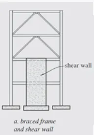
Total length of column = 10 m.
Length of column in each floor = 2.5m.
Assume length of beam at each level = 2.5m.
Consider the same section is used for all members in the frame.
Using the substitute frame method to find β1 and β2 for the columns in the frame.
So, the stiffness of all columns Kc = I/L.
Stiffness of all beams Kb = 0.5I/L (Since it is a braced frame)
As length and moment of inertia of both beams and columns are equal Kb = 0.5Kc
At beam-column joints, (left and right side)
β = `(∑Kc)/(∑Kc+∑Kb)`
β = Kc/(Kc+Kb) = Kc/Kc+0.5Kc = 0.67 (For the elevation 10m).
β = Kc+Kc/(Kc+Kc+Kb) = 2Kc/2Kc+0.5Kc = 0.8 (For the elevation 7.5m, 5m and 2.5m).
β = 0 (At fixed base)
For the columns between elevation 10m and 7.5m.
β1 = 0.67, β2 = 0.8
Effective length factor K = 0.8 From Fig 27 : Column Effective length factor - Non sway frame, Annexure - D, IS 800.
For the columns between elevation 7.5m - 5m and 5m to 2.5m.
β1 = 0.8, β2 = 0.8
Effective length factor K = 0.8 From Fig 27 : Column Effective length factor - Non sway frame, Annexure - D, IS 800.
For the columns between elevation 2.5m to 0m.
β1 = 0.8, β2 = 0
Effective length factor K = 0.65 From Fig 27 : Column Effective length factor - Non sway frame, Annexure - D, IS 800.
b)
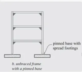
Total length of column = 10 m.
Length of column in each floor = 3.33m.
Assume length of beam at each level = 3.33m.
Consider the same section is used for all members in the frame.
Using the substitute frame method to find β1 and β2 for the columns in the frame.
So, the stiffness of all columns Kc = I/L.
Stiffness of all beams Kb = 1.5I/L (Since it is a unbraced frame)
As length and moment of inertia of both beams and columns are equal Kb = 1.5Kc
At beam-column joints, (left and right side)
β = `(∑Kc)/(∑Kc+∑Kb)`
β = Kc/(Kc+Kb) = Kc/Kc+1.5Kc = 0.4 (For the elevation 10m).
β = Kc+Kc/(Kc+Kc+Kb) = 2Kc/2Kc+1.5Kc = 0.57 (For the elevation 6.6m and 3.3m).
β = 1 (At pinned base)
For the columns between elevation 10m - 6.6m.
β1 = 0.4, β2 = 0.57
Effective length factor K = 1.47 From Fig 28 : Column Effective length factor - Sway frame, Annexure - D, IS 800.
For the columns between elevation 6.6m - 3.3m.
β1 = 0.57, β2 = 0.57
Effective length factor K = 1.6 From Fig 28 : Column Effective length factor - Sway frame, Annexure - D, IS 800.
For the columns between elevation 3.3m - 0m.
β1 = 0.57, β2 = 1
Effective length factor K = 2.68 From Fig 28 : Column Effective length factor - Sway frame, Annexure - D, IS 800.
c)
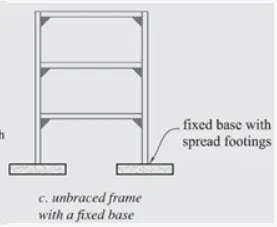
Total length of column = 10 m.
Length of column in each floor = 3.33m.
Assume length of beam at each level = 3.33m.
Consider the same section is used for all members in the frame.
Using the substitute frame method to find β1 and β2 for the columns in the frame.
So, the stiffness of all columns Kc = I/L.
Stiffness of all beams Kb = 1.5I/L (Since it is a unbraced frame)
As length and moment of inertia of both beams and columns are equal Kb = 1.5Kc
At beam-column joints, (left and right side)
β = `(∑Kc)/(∑Kc+∑Kb)`
β = Kc/(Kc+Kb) = Kc/Kc+1.5Kc = 0.4 (For the elevation 10m).
β = Kc+Kc/(Kc+Kc+Kb) = 2Kc/2Kc+1.5Kc = 0.57 (For the elevation 6.6m and 3.3m).
β = 0(At fixed base)
For the columns between elevation 10m - 6.6m.
β1 = 0.4, β2 = 0.57
Effective length factor K = 1.47 From Fig 28 : Column Effective length factor - Sway frame, Annexure - D, IS 800.
For the columns between elevation 6.6m - 3.3m.
β1 = 0.57, β2 = 0.57
Effective length factor K = 1.6 From Fig 28 : Column Effective length factor - Sway frame, Annexure - D, IS 800.
For the columns between elevation 3.3m - 0m.
β1 = 0.57, β2 = 0
Effective length factor K = 1.28 From Fig 28 : Column Effective length factor - Sway frame, Annexure - D, IS 800.
RESULT :
a) For the braced fame :
For the columns between elevation 10m and 7.5m.
Effective length factor K = 0.8
For the columns between elevation 7.5m - 5m and 5m to 2.5m.
Effective length factor K = 0.8
For the columns between elevation 2.5m to 0m.
Effective length factor K = 0.65
b) For the unbraced frame with pinned base :
For the columns between elevation 10m - 6.6m.
Effective length factor K = 1.47
For the columns between elevation 6.6m - 3.3m.
Effective length factor K = 1.6
For the columns between elevation 3.3m - 0m.
Effective length factor K = 2.68
c) For the unbraced frame with pinned base :
For the columns between elevation 10m - 6.6m.
Effective length factor K = 1.47
For the columns between elevation 6.6m - 3.3m.
Effective length factor K = 1.6
For the columns between elevation 3.3m - 0m.
Effective length factor K = 1.28
2) AIM : To find out the compression carrying capacity of ISMB 300 with flange cover plate of 200 * 12 mm on each flange.
INTRODUCTION : Bottom of column is fixed and top of column is roller. So, the effective length factor is 1.2
K = 1.2
Length of column = 3m
Yied strength of column = 250 N/mm2.
PROCEDURE : Given section is builtup member. So, the buckling class is 'c'.
For the given builtup section, minimum radius of gyration is obtained from Table 11 of Steel Tables.
rmin = 44.4 mm.
Slenderness ratio SR = `(K*L)/(rmin)` = `(1.2*3*1000)/44.4` = 81.08
From Table 9c, fcd = 136 N/mm2 for SR = 80 and fcd = 121 for SR = 90. By interpolating final design compressive stress is
fcd = 134.38 N/mm2.
Sectional Area A = 10426mm2. from Table 11 of Steel Tables
Design Compressive Strength of column Pd= `fcd*A` = 1401.046 KN
Axial Compressive Capacity of given column = Pd/1.5 = 934.03 KN
RESULT : Axial Compressive Capacity of given column = 934.03 KN
3) AIM : To design the long circular tubular strut member to carry factored load of 400 KN. Also to find out the equivalent square hollow section.
INTRODUCTION :
Length of member L = 2m.
Factored axial load P = 400 KN.
Both ends of member are simply supported. Hence effective length factor K = 1.
Yield Strength of member fy= 210 N/mm2.
PROCEDURE :
Assume design compressive stress = 0.6*fy = 126 N/mm2.
Effective sectional area Ae = `(P)/(fcd)` = 3174.603 mm2 = 31.74 cm2.
Case A) Based on the required effective sectional area, the CHS 200 of 4.8 mm thickness is required.
Effective sectional area of CHS 200 of 4.8 mm thickness Ae = 32.33 cm2.
Radius of Gyration R = 7.58 cm
Slenderness Ratio = (K*L)/R = 26.38
Section is circular hollow section and assuming it is hot rolled section. So, from Table 10 of IS 800 the buckling class is classified as a.
From table 9a, design compressive stress is obtained
fcd = 187.81 N/mm2.
Axial Compressive strength of member Pd= fcd*Ae = (187.81*3233)/1000 = 607.19 KN.
So, P < Pd. Hence design is safe.
Case B) Trying square hollow section, the section 150*150*6 mm carries axial compressive load of 617.011 KN
Hence Pd = 617.011 KN > P = 400 KN.
So, the choosen section is safe
Note : The same procedure is repeated by selecting smaller sections to select optimum sections for the above two cases A and B.
RESULT : The hollow sections required to carry factored load of 400 KN are
1) CHS 200*4.8 mm.
2) SHS 150*150*6 mm.
4) AIM : Design of Laced column to carry the factored load of 1000 KN.
INTRODUCTION : Factored load Pu = 1000 KN.
Height of column H = 10m.
PROCEDURE : Consider design compressive stress fcd = 150 N/mm2.
Area required A = Pu/fcd = 6666.7 N/mm2.
Let us try two ISMC 300 channel sections back to back.
Radius of gyration about zz axis rzz = 118.1 mm, A = 4564 mm2.
Effective Slenderness ratio = 1.05*H/rzz = 1.05*10*1000/118.1 = 88.91
Assume fy = 250 N/mm2.
From Table 9c, fcd = 121 N/mm2.
Pd = fcd *(2*A) = 1104 KN > 1000 KN. Hence safe.
Consider horizantol axis as z axis and vertical axis as y axis.
Step 1 : Spacing of channel sections back to back.
Lacing is a builtup member. So, the spacing of the two channels can be obtained can be obtained by equating moment of inertia about both the z axis and y axis.
Total moment of inertia about z axis = 2*Izz ------ (1)
Total moment of inertia about y axis = `2[Iyy + A (s/2 + cyy)^2]` -------- (2) (This equation is obtained with the help of parallel axis theorem) where A is area of channel section, s is spacing, cyy is the centre of gravity.
From SP6,
Izz = 6362.6 cm^4, Iyy = 310.8 cm^4, A = 45.64 cm^2 cyy = 2.36 cm.
Equating (1) and (2), we get spacing of channels s = 183.1 mm = 184 mm.
Step 2 : Spacing of Lacings
Angle of lacing = 45 deg.
Consider gauge distance g = 50 mm
a = s + 2g = 284 mm.
Spacing of lacings L = 2a/tanθ = 568 mm.
rzz = 11.81 cm, ryy = 2.61 cm
Effective Slenderness ratio of coulmn Λmax = 1.05*H/rzz = 1.05*10000/118.1 = 88.91 < 180
0.7*Λmax = 62.24.
L/rmin < min(0.7*Λmax, 50)
L/26.1 = 50 . So, L = 1305 mm > 568 mm. Hence Spacing of lacings L = 568 mm.
Step 3 : Length of lacing
`nbsp; l = a/sinθ = 401.64 mm`
Step 4 : Thickness of lacing t = l/40 = 10.05 mm So, minumum thickness = 12 mm.
Slenderness ratio of lacing is restricted to 145.
So, Λlacing = `(l eff * sqrt(12))/t` = 116 < 145 . Hence safe.
Assume diameter of bolt d = 16 mm
Width of lacing bar b = 3*16 = 48 mm. Consider Width of lacing bar b = 50 mm.
Step 5 : Transverse shear Vt = 2.5% of factored load = 25KN
Axial force Fc = Vt/2sinθ = 17.67 KN.
Step 6 : From Table 9c of IS 800 : 2007, fcd = 88 N/mm2. (Assume fy = 250 N/mm2)
Compressive design strength of lacing Pd = Ae*fcd = b*t*fcd = 52.84 KN > 17.67 KN.
Step 7 : Check for tensile strength of lacing
Tdg = Ag*fy/γm0 = 50*12*250/1.1 = 136.36 KN.
Tdn = 0.9*(b-dn)*t*fu/γm1 = 0.9*(50-2(12))*12*410/1.25 = 92.10 KN
Hence Td = 92.10 KN > 17.67 KN.
Result : Width of lacing member b = 50 mm.
Thickness of lacing member t = 12 mm.
length of lacing member l = 401.64 mm.
Spacing of lacing bars L = 568mm.
5) AIM : To design battened column.
INTRODUCTION : Height of battened column = 5m.
Factored axial load acting on the column Pu = 2000 KN.
PROCEDURE :
Step1 : Design compressive stress fcd = 175 N/mm2 (Assumption)
Area of cross section required A = Pu/fcd = 11428.57 mm2.
Let us try two ISMC channel sections.
Cross sectional area of ISMC 400 channel = 6293 mm2.
rxx = 154.8mm ryy = 28.3 mm
Total area Ae = 2*6293 = 12586 mm2.
Slenderness ratio K = L/rzz = 5000/154.8 = 32.30
Effective slenderness ratio Ke = 1.1*32.30 = 35.53 < 180 (Hence safe)
Yield stress fy = 250 N/mm2. (Assumption)
Buckling class 'c'
Design compressive stress fcd = 204.5 N/mm2 (From Table 9c - IS 800)
Compressive strength Pd = Pd* Ae = 2573.84 KN > Pu = 2000 KN (Hence safe)
Step 2 : Spacing of channel sections 'S'
Ixx = 15082.8 cm^4, Iyy = 504.8 cm^4, Cyy = 24.2 mm (From SP 6).
2Ixx = 2[Iyy+A(s/2 + Cyy)^2]
Solving the above equation, we get s = 256 mm.
Step 3 : Spacing of battens C
C/rmin < 0.7*Ke => C < 0.7* 35.53 * 28.3 => C < 703.85 mm
C/rmin < 50 => C < 28.3 * 50 => C < 1415 mm.
Hence C= 700 mm (Minimum of above two values)
Step 4 : Thickness of batten 't'
t = 256/50 = 5.12 mm
Hence provide thickness of batten t = 6mm.
Overlap Lp > 4 * t = 24 mm.
Provide Lp = 100 mm
Step 5 : End batten
Length of batten L = s + 2*Lp = 456 mm
Effective depth of batten = S + 2*Cyy = 304.4 mm
End distance = 50 mm (Assumption)
Overall depth of batten D = 304.4 + 2* 50 = 404.4 mm.
Size of end batten = 456 *405* 6
Step 6 : Intermediate batten
Effective depth of batten = 0.75(s + 2*Cyy) = 0.75*304.4 = 228.3 mm
End distance = 50 mm (Assumption)
Overall depth of batten D = 228.3 + 2* 50 = 328.3 mm.
Size of Intermediate batten = 456 *330 *6
Step 7 : Longitudinal shear (Vl) and Moment (M)
Transverse shear Vt = 2.5% of Pu = 50000 N
Spacing of battens C = 700 mm.
N = N. of parallel planes of battens = 2.
Minimum transverse distance between the centroid of Weld group S = s + 2*50 = 356 mm
Longitudinal shear Vl = V*C/N*S = 49157.30 N
Moment M = V*C/2*N = 8.75 * 10^6 N mm.
Step 8 : Check
Permissible bending stress = fy/1.1 = 227.27 N/mm2
Permissible shear stress = `(fy)/(sqrt(3)*1.1` = 131.22 N/mm2
i) For End battens
Shear stress = 49157.3/(405*6) = 20.23 N/mm2 < 131.22 N/mm2 (Hence safe)
Bending stress = 6M/td^2 = 53.35 N/mm2 < 227.27 N/mm2 (Hence safe)
ii) For Intermediate battens
Shear stress = 49157.3/(330*6) = 24.83 N/mm2 < 131.22 N/mm2 (Hence safe)
Bending stress = 6M/td^2 = 80.34 N/mm2 < 227.27 N/mm2 (Hence safe)
Result : Size of End battens = 456*405*6 mm3
Size of Intermediate battens = 456*330*6 mm3
Two ISMC 400 channel sections back to back.
Spacing of channel sections = 256 mm.
Spacing of battens = 700 mm.