Week - 4
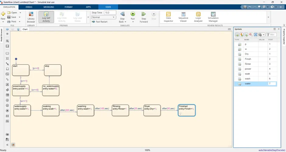
1) Aim: to implement control logic of a washing machine using Stateflow, power supply is available the system gets activated. If the water supply is not available stop the process &indicate through LED. Soaking time should be 200s followed by washing time of 100s,then rinsing happens for next 20s &dryer runs for 50s
Blocks used:
· Rocker switch
· Constant block
· Stateflow chart
· Display
· Lamp
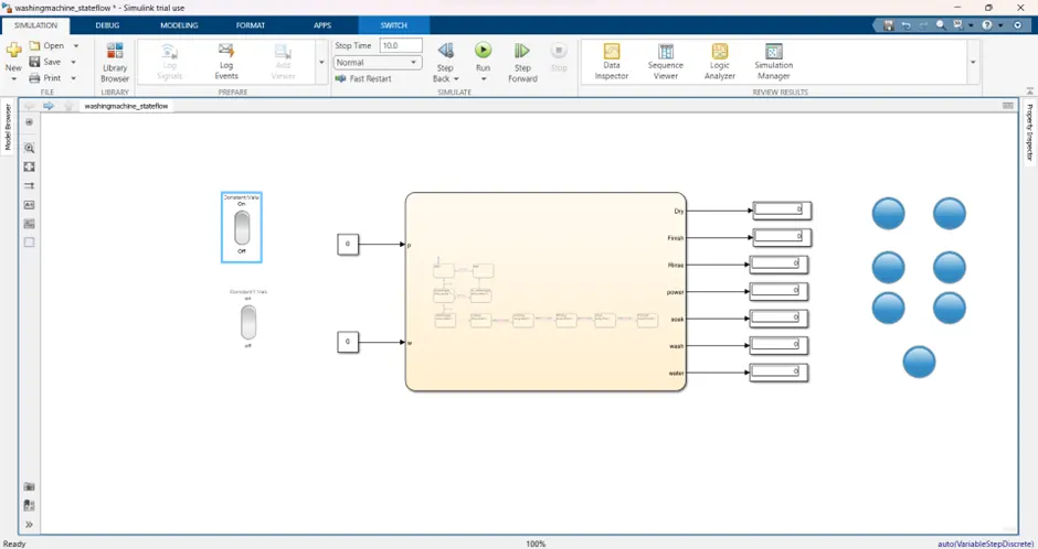
Block construction: The rocker switch is connected with a constant block which has a power supply and water supply created in the Stateflow chart of the washing machine. by giving a symbol plan all the states will be given in the right corner of the state flow diagram. List the output and input block
s and result in the washing machine chart block their display will be connected to the output
port. the lamp is connected to the display. by satisfying the condition
Simulation model:
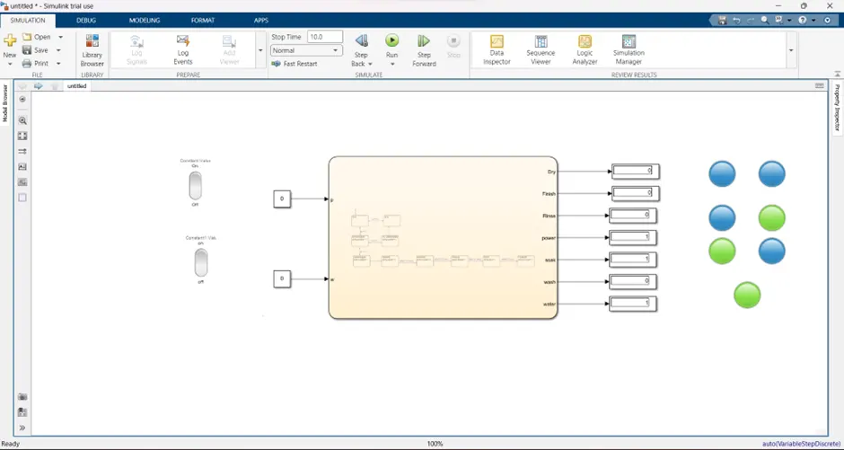
Simulation result:
Stateflow diagram:
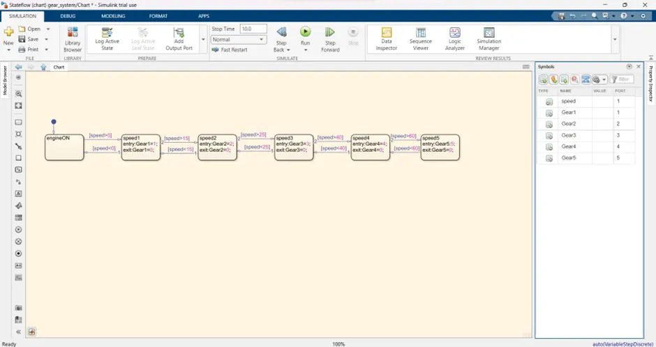
1) Aim: make a simulation chart for the gear shift logic as per given condition,
Speed range - 0-15,16-25,26-40, 41-60, above 60
Gear – 1,2 3, 4,5.
Based on the display input simulation is running & displays the gear number.
Block used:
· Constant block
· Stateflow chart block
· Slider
· Display
· lamp
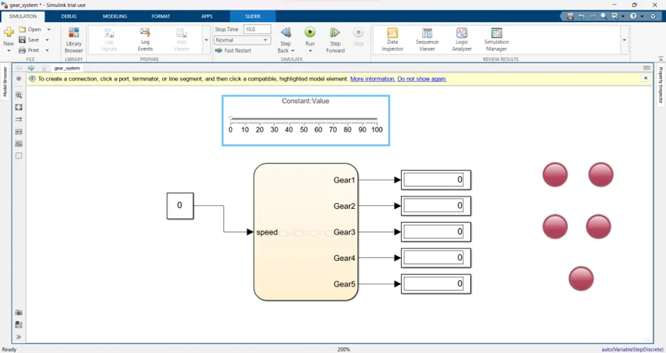
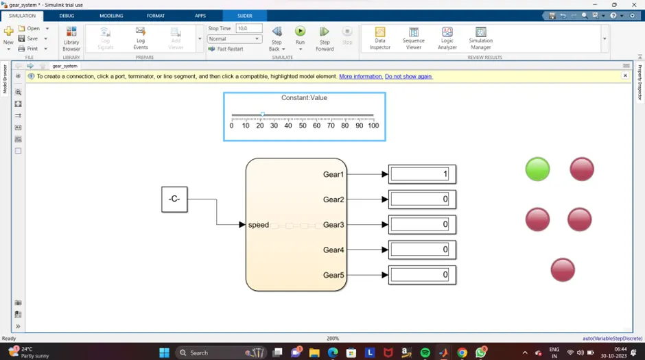
construction: The constant block is connected with the Stateflow block where the five gear out is given that the output port is connected to the display. and then the display is connected to the lamp. connect the slider to the constant block. based on the condition the output will differ and the lamp glow also differ
simulation model:
Simulation output:
Stateflow model: