Project
Aim: To carry out System level simulation of an all-terrain vehicle . To built an AVT with CVT used in Baja . simscape driveline is used to complete the system . The engine speed vs torque curve is obtained using engine data in the model.
Components of Baja ATV:
· Vehicle body
· Suspension
· Tire
· Engine
· CVT
Blocks used :
Brake and throttle input -Signal builder
· From block & Goto block
· Solver configuration
· Mechanical Rotational Reference
· Generic engine block
· Engine sensor block
· CVT block
· Simple Gear
· Vehicle body block
· Engine Torque speed curve block
· Scope.
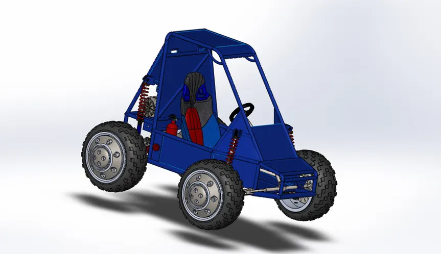
Model of Baja All-terrain Vehicle (AVT model):
Concept of CVT:
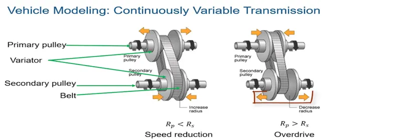
· CVT consists of four major parts. Primary pulley, variator, Secondary variator, and belt.
· Speed Reduction: The primary pulley is connected to the variator if it moves outward the variator of secondary pulley moves inward such that the radius of the primary pulley is less then secondary pulley which results in speed Reduction.
· Overdrive: The primary pulley connected with variator moves inward and the variator of the secondary pulley moves outwards which results in overdrive
Simulation model:
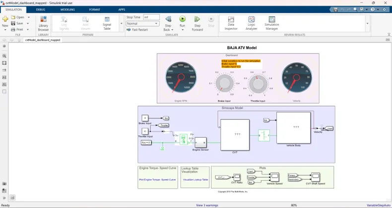
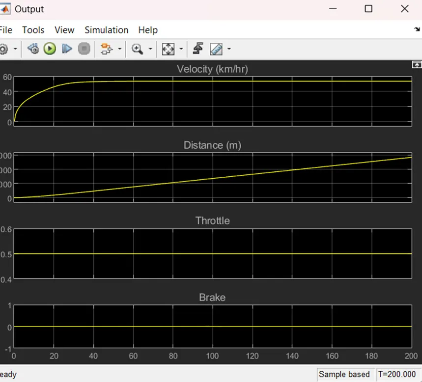
By changing the throttle or brake input the vehicle and RPM are changed and the gear ratio is obtained by vehicle velocity, engine torque, engine RPM
Block explanation :
CVT Model:
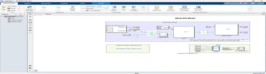
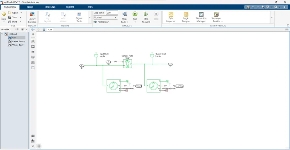
Two type of model is implemented one is open loop and another one is closed loop . There will be Feedback from the velocity to the CVT model. Inside CVT is based on lookup table given along with the model and another block connected is the CVT input ratio .
Subsystems :
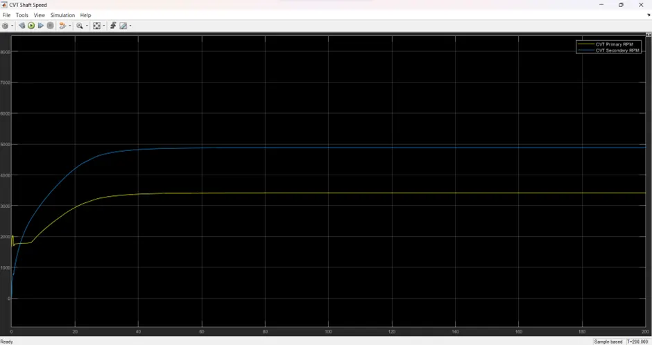
CVT – the input shaft inertia and output shaft inertia represents the primary and secondary pulley . the variable gear ratio is implemented here .
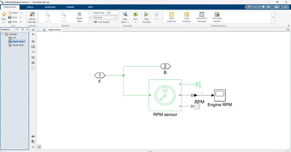
Engine Sensor: vector speed is input and torque vector is given by torque speed curve
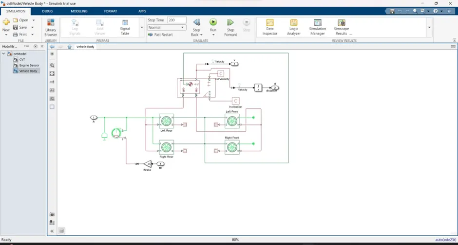
Vehicle body-
Inputs :
Brake and throttle input-
· The Brake input is 0 and the throttle input is given from 0.2 to 0.5.
· Input can be varied by the nob present in the dashboard
CVT gear ratio :
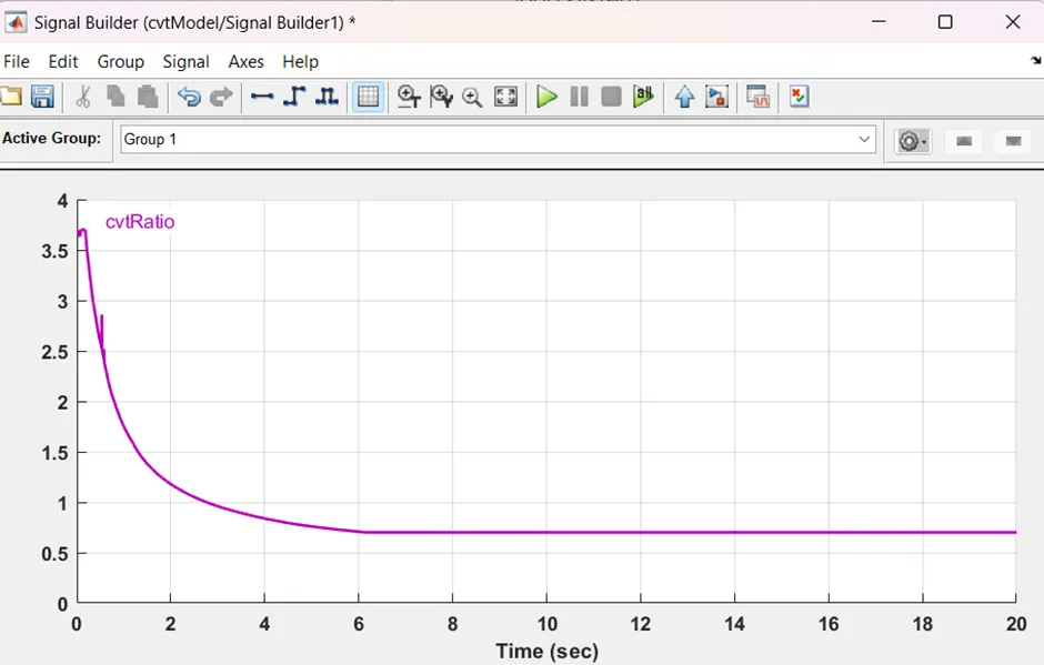
Random CVTratio as input and check the velocity.the input can be changed by building the signal in the signal builder block. The input can be changed using a lookup table this is applicable in a closed-loop system
Engine torque -speed curve :
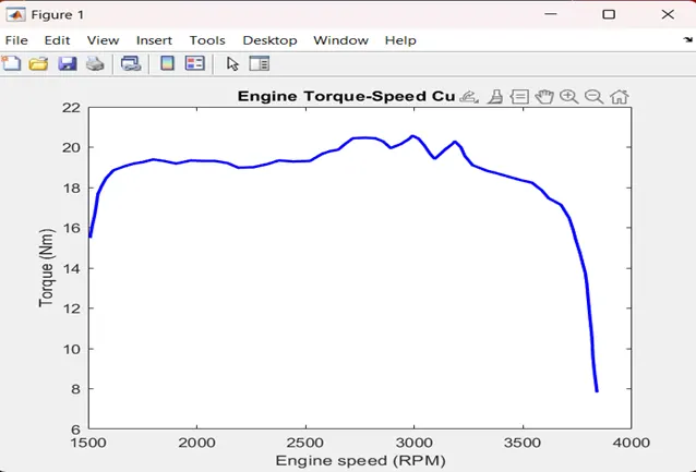
The engine input value is the speed vector and torque vector .
Output:
CVT shaft speed :
Result :
· We can conclude that the CVT model gear ratio of 4 applies.
· The output plot represents with this parameter appropriate system that can be built.