Week - 4
Aim: Implement control logic using Stateflow using.
Task 1
To implement control logic of a washing machine using stateflow as per given sequence.
Objective:
- If the power supply is available, the system gets activated.
- If the water supply is not available, stop the process & indicate through LED.
- Soaking time should be 200s followed by washing time of 100sec.
- Then rinsing happens for the next 20 sec and the dryer runs for 50 sec.
- After process completion have to turn on the LED.
Control logic used in washing machine:
- Stateflow chart.
- Power supply is given to the system as PowerSwitch==1 which power is on PowerSwitch==0 in which power is off.
- W==1 & W==0 is used to know whether water is available or not. When both are active then the machine gets started running.
- Then next four states are created for the flow order of the Soaking, Washing, Sinking, Drying with their time of operation for soaking 200 sec, for washing 100 sec, for rinsing 20 sec and for drying 50 sec. After all the process is done then its all shown through Lamp, and then we can shut the machine off.
- At the entry of power one line is connected with the no water block which indicates no water in the tube and sends a feedback.
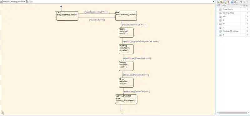
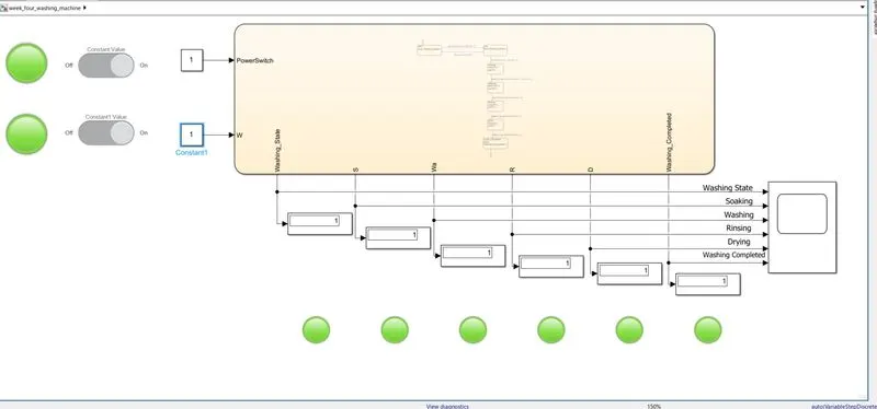
- Simulink model of washing machine.
- OFF condition of washing machine.
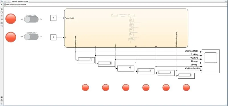
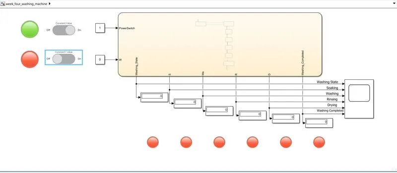
- Power is given is on & water supply is OFF of the washing machine.
- Water supply is ONN & the washing machine starts working.
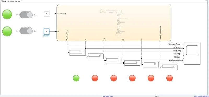
- The washing machine is running.
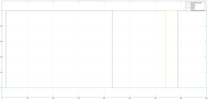
Result:
Task 2:
To make a Simulink chart of a “Gear shift” logic as per given conditions.
Conditions:
| Speed Range(kmph) | Gear |
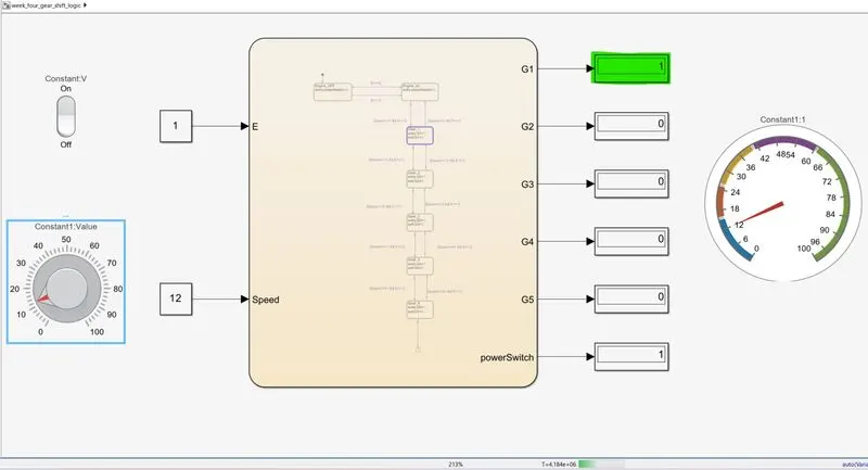
| 0 to 15 | 1 |
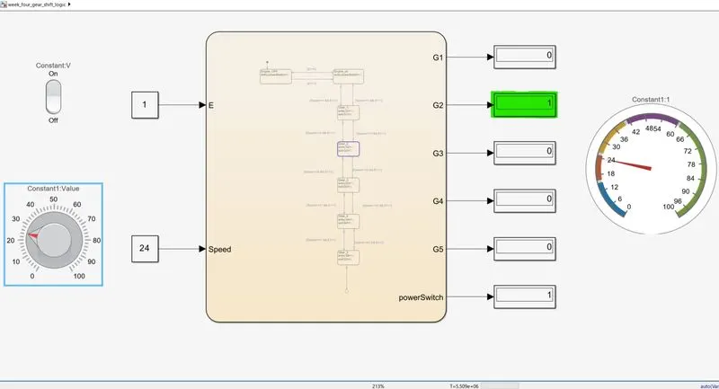
| 16 to 25 | 2 |
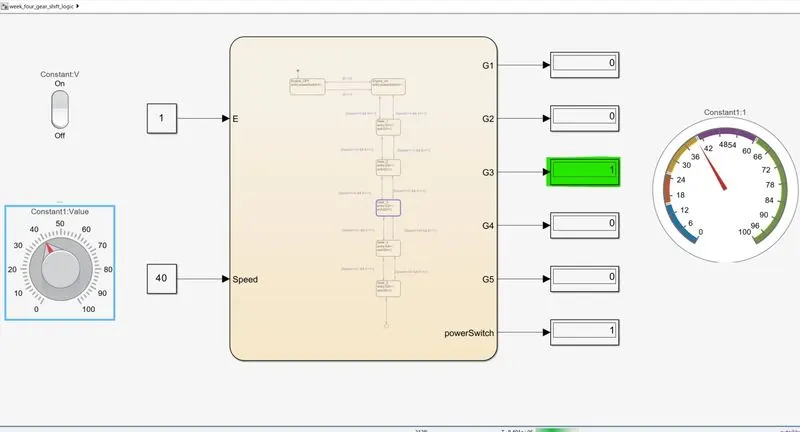
| 26 to 40 | 3 |
| 41 to 60 | 4 |
| Above 61 | 5 |
Theory:
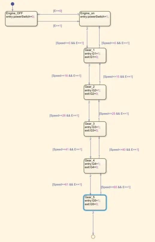
In this system a speed range is 0-100 so we use Knob block for giving input speed. The first gear speed range is 0 to 15 so the entry of state for the 1st gear is 0<=speed and 15>=speed it is the exit condition of gear in speed greater than 15. In gear 2 entry state is 16<=speed and 25<=speed the exit condition is between speed<16 to speed<25. In gear 3 entry state is 26<=speed and 40<=speed the exit condition is between speed<26 to speed<40.In gear 2 entry state is 41<=speed and 60<=speed the exit condition is between speed<41 to speed<60. In gear 5 entry state is 61<=speed the exit condition is between speed >=60.
Control logic used in Gear shifting:
- Stateflow chart
- Control logic
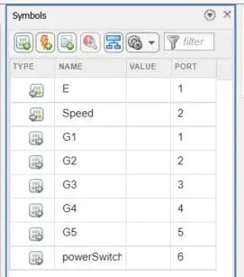
- Symbols
- Control logic
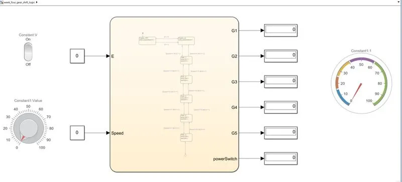
- OFF condition of engine.
- Speed range is 0 to 15 in 1st gear.
- Speed range is 16 to 25 in 2nd gear.
- Speed range is 26 to 40 in 3rd gear.
- Speed range is 41 to 60 in 4th gear.
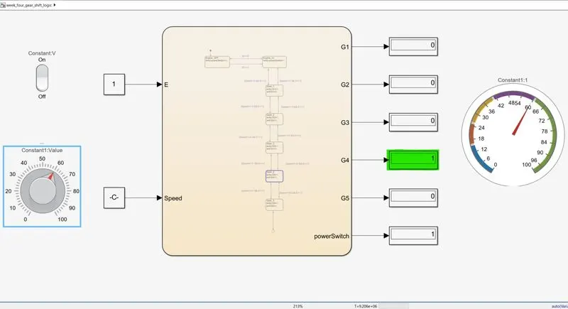
- Speed range is above 61 in 5th gear.
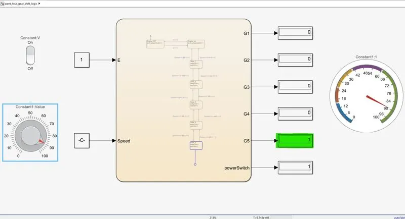
Conclusion:
Hence washing machine and gear shifting conditions are simulated through stateflow charts successfully.