Week - 4
- Implement control logic of a “washing machine” using Stateflow as per given sequence:
- If the power supply is available, the system gets activated
- If the Water supply is not available, stop the process & indicate through LED
- Soaking time should be 200s followed by Washing time of 100s.
- Then rinsing happens for next 20s & dryer runs for 50s
After all the processes have completed turn on the finished LED.
ANSWER:
The washing machine is a machine used to wash various types of clothes without applying any physical effort. With a washing machine, you don’t have to rub the clothes with your hand or squeeze them to remove the water from them. The washing machine is also called a clothes washer or simply a washer. The washing machine enables you to wash your clothes automatically without having to supervise its operation. All you have to do is put the clothes in the machine and select the wash mode. The washing machine automatically takes in the amount of water and detergent required and it also automatically sets the timer for washing, rinsing, and drying as per the selected mode and the number of clothes.
Stages of washing machine:
- Prewash
- Washing
- Rinsing
- Spinning
Prewash
The option called prewash indicated filling the drum with a certain water level and mix up with the detergent powder. All this option helps to wash out all the stains including the stubborn or dirt very well from the clothes. This is possible as we soak the whole clothes placed into the drum. Finally, drain the water without making a second thought.
Taking the amount of water is different for both front load and top load washers respectively. In the front-load washing machines, it is all up to the settings done by the single user. Whereas at the top load washers, there are water level sensors for filling the drum at a certain level and clean the entire load getting rid of stubborn stains successfully.
Washing
At this particular time, the machine uses agitation which is for mixing both water and detergent, in turn moving the clothes all around the drum. Generally, the top load washing machines come with an agitator or impeller placed at the center of the tub.While coming to front-load washers, it depends upon the rotation of the entire tub provided for enhancing better wash and cleaning the load ultimately. Moreover, the duration taken to complete the wash cycle is depends upon the settings option chosen by the user. Always the heavy load enhances high duration. Small or limited load enhances less duration.
Rinsing
The option called rinsing is known for the multi-talented option. During this particular cycle is on the flow, the soapy water taken from the clothes. And all the fresh or pure water is sparkled to the clothing available in the tub. This particular rinse option held responsible for taking soapy water out of the washer without facing any kind of difficulties. Finally, the agitation with plain water is considered the last step in the rinsing option.
Spinning
Spinning is done to dry the entire clothes before getting to the end of the actual wash cycle. And these several washing machines are going to be spun at different speeds. In turn, the speed of one particular spin is calculated in revolutions per minute (rpm) respectively. This indicates the speed of the spin extracting the whole amount of water from the clothes making it dry very well.
These are the different cycles done by each model available in the Indian market. Accordingly, the machine coming with these factors enhances high performance. All the things one should aware of these options and must pick the right one at the right time. For any doubts, mention a single comment in the following rectangular section.
So that we help you understand the terminology much better comparatively. Thank you. If you like to learn more interesting things related to washing machines, keep in touch with the best washing machine irrespective of time and place.
Modeling of Washing machine in Simulink:
these are the following things we need for modeling the subs system of washing machine logical block settings:
- Toggle switch
- Constant
- State flow chart
- Lamps
- Display
Now following with steps involves in the process we go step by step:
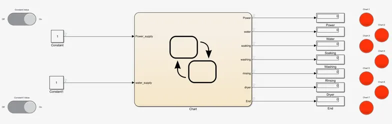
1. Switced OFF when non opertaional:
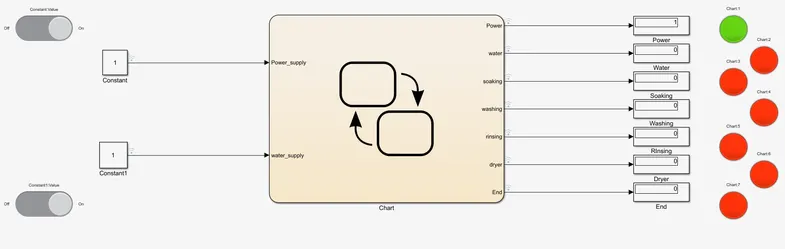
- 2. Power ON
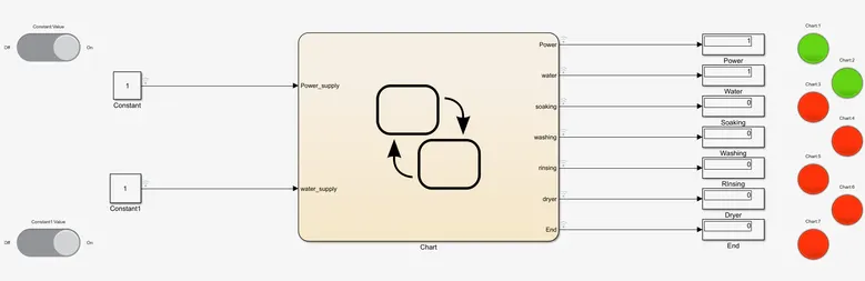
- Water Supply ON
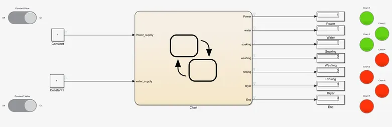
- . Soaking
- Washing ON
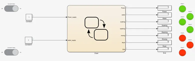
- Rinsing
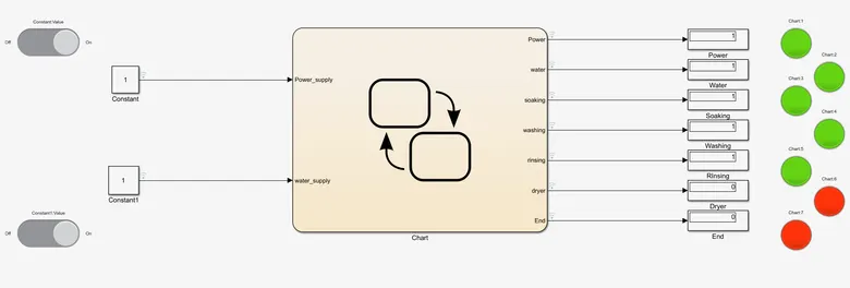
- Drying
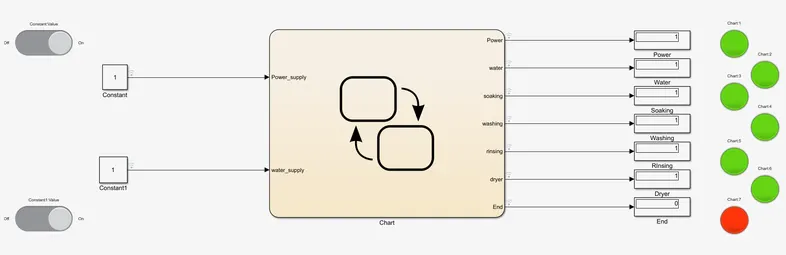
- END process
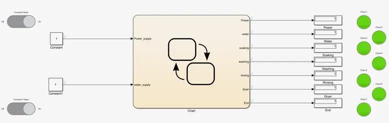
-
This is what it looks like in the State flow chart:
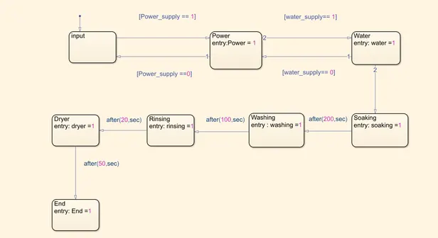
Just according to every step we define here execute accordingly.
2. Make a Simulink chart for the “Gear shift” logic as per below conditions:
Speed Range(kmph) Gear
0 to 15 1
16 to 25 2
26 to 40 3
41 to 60 4
Above 61 5
Give speed input while the simulation is running & display the gear number.
ANSWER: In this system mainly used as slider block. It is used for the given input to speed.- LOGIC SYSTEM:
-
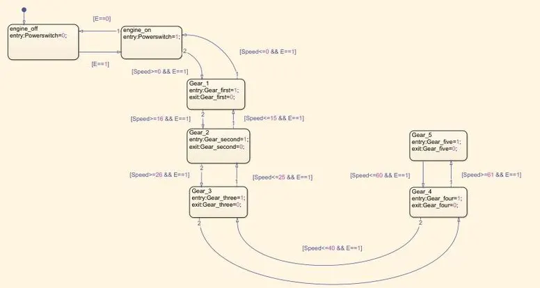
In this system given speed range is 0-100 so we use slider block for the given input speed. The first gear speed range is 0 to 15 so the entry of state for the 1st gear is 0<=speed and 15>=speed it is the exit condition of gear in speed greater than 15. In gear 2 entry state is 16<=speed and 25<=speed the exit condition is between speed<16 to speed<25.Same conditions are applied in all gears and the output is gives from lamp and display block.
- FLOWCHART:
-
In the above flowchart first start the engine creating input switch E=0/1 through rocker switch which is gives the powerto engine. then next gear shift logic is implemented through following states. The five gear states are created in system as gear 1,2,3,4,and 5 rsesp. and their trasition is connected with speed range condition is shown below
The gear transition is decided below
Speed>15 shift to G=2
Speed>25 shift to G=3
Speed>40 shift to G=4
Speed>60 shift to G=5 when the speed increasing from 0-60kmph simillarly in reverse direction as same.
while simulating gear shifting logic engine E==0 condition given to various speed change values. - SYMBOL:
-
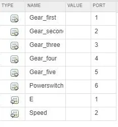
In this output as gear_first, Gear_second, Gear_third, Gear_fourth, Gear_fifith and the input is E, and speed.
- STEP1:
-
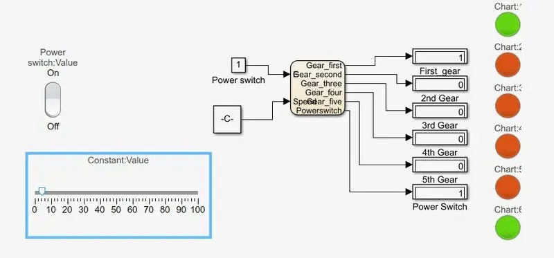
In this model we shown when the engine start and the speed is goes to 5kmph then the model shown at that speed the engine is it at 1st gear it is indicated through lamp.
- STEP2:
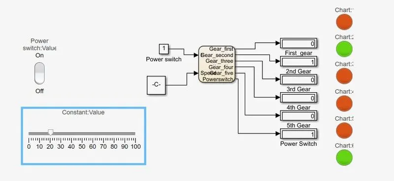
-
In this model speed is 20kmph and it is in 2nd gear the see the only second lamp is on.
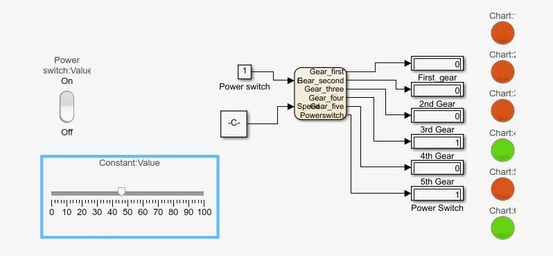
- It is at speed nearly 45kmph at engine in 3rd gear and glow green light and display output as 1
- STEP4:
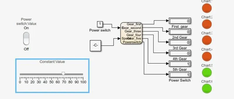
In this model the speed of engine is at above 60 then the gear is implemented as 5th and the green light was on and in display block showing 1.