Week - 4
Objective:
1. Implement control logic of a “washing machine” using Stateflow
2. Make a Simulink chart for the “Gear shift” logic.
Theory: Case 1- Implement control logic of a “washing machine” using Stateflow
The working principle for the washing machine is "Centrifugation". Centrifugation is a separation process that uses the action of centrifugal force to promote accelerated settling of particles in a solid-liquid mixture. The washing machine consists of a centrifuge for this purpose. A centrifuge is a piece of equipment that puts an object in rotation around a fixed axis, applying a force perpendicular to the axis of spin that can be very strong.
Inside the Washing machine, there are few processes which are carried out in a successive period of time such as
a) Soaking
b) Washing
c) Rinsing
d) Drying
Simulink Model: Case-1
Stateflow Chart- A finite-state machine is a representation of an event-driven system. In an event-driven system, the system responds to an event by making a transition from one state to another. This transition happens if the condition provided is true. A state flow chart is a graphical representation of a finite state machine.
State flow chart of the Washing Machine Model:
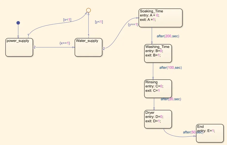
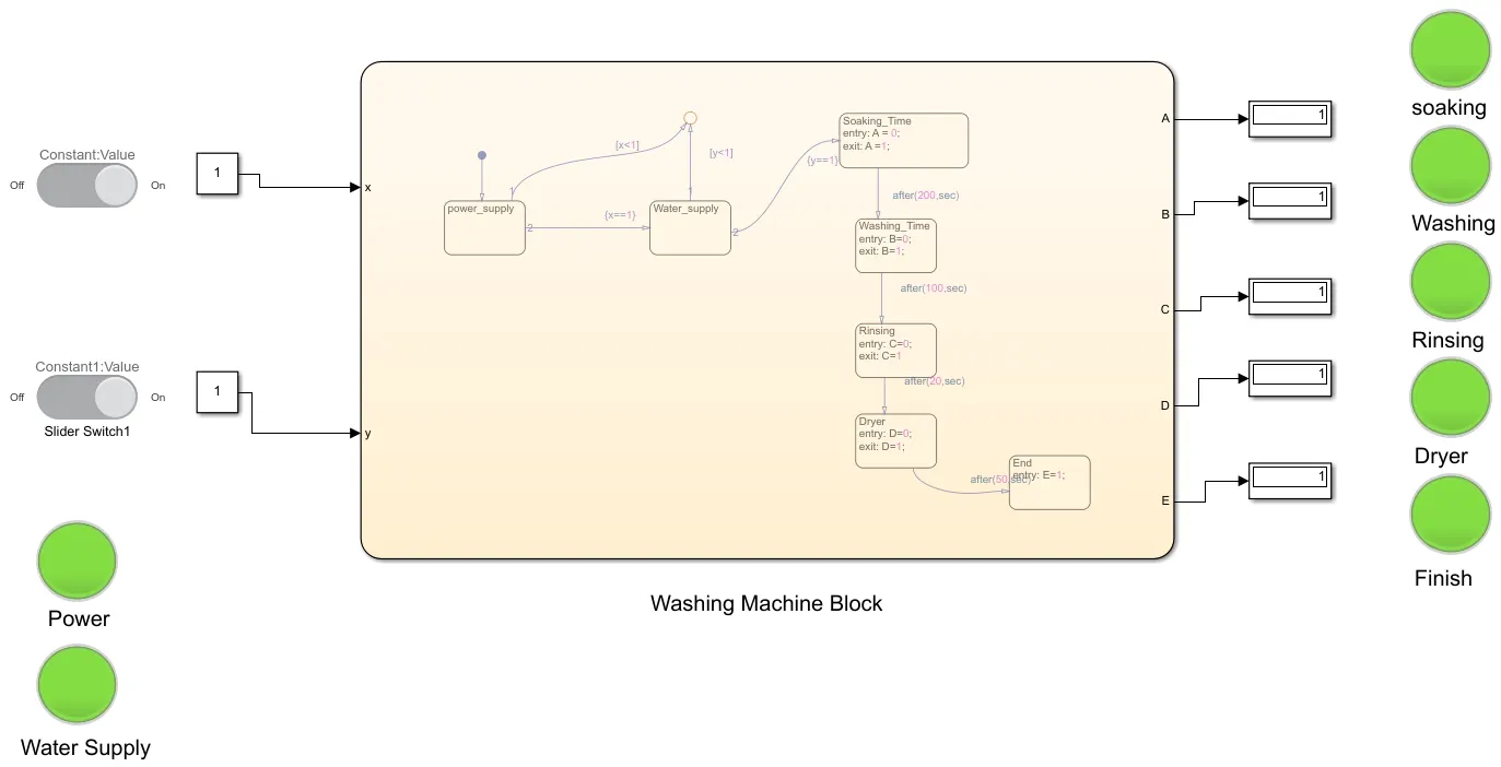
Explanation: Since in the question it is clearly stated that only when the Power is on the whole process will begin. This is followed by the availability of the water supply. If either of these 2 conditions is not satisfied the washing machine process will not begin.
Hence the only the positive condition is connected to the process while the negative condition is connected to a separate junction. Again as per the question, the first process soaking is carried for 200 seconds which is represented as "after(200,sec)", the heading for this block can be assigned as per the block requirement. I have given the entry value as "0" and the exit value as "1". The same process is carried till the "Dryer" process then finally the End block with an entry value of "1".
The is the final Simulink model for the Washing Machine
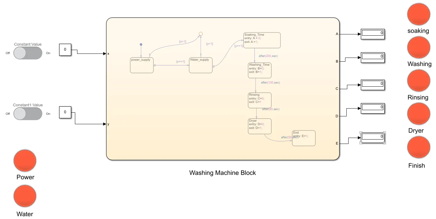
2 constant block has been connected to the state flow chart as inputs. These 2 constant blocks are in turn controlled by a "Slider switch" (which on sliding towards 'on' provides the value 1 and when towards 'off' provides the value 0). 5 outputs are connected from the state flow chart to the display. These 5 outputs indicate the 4 different processes that are happening inside the washing machine (Soaking, Washing, Rinsing and Dryer) and the last one is the finish.
Both the inputs and outputs are connected to a Lamp, which is defined in a way that it emits green light when the output is 1 and emits red light when the output is 0.
Results: Case 1
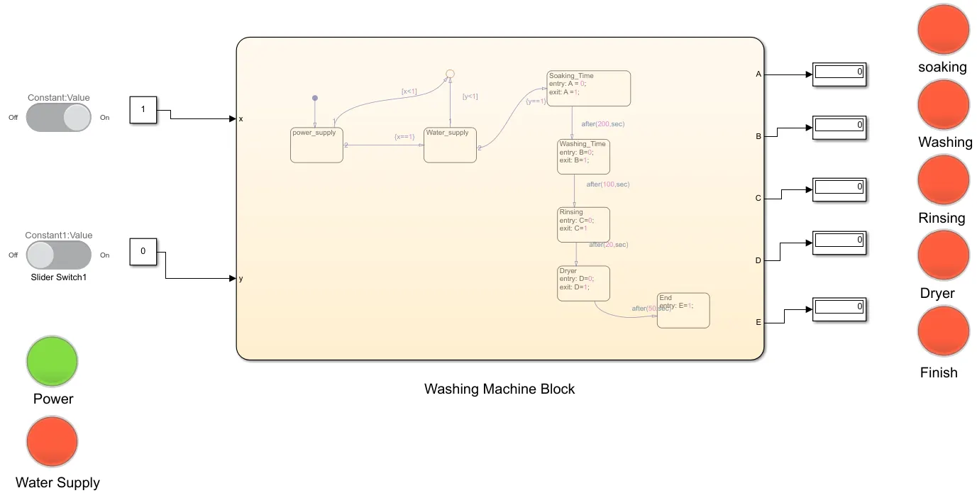
1. Here I switched on the slider switch for the power, but as per the question if the water supply is not turned on then the whole process cannot begin. Hence in the below-shown Simulink block, except the power button rest all is in red color.
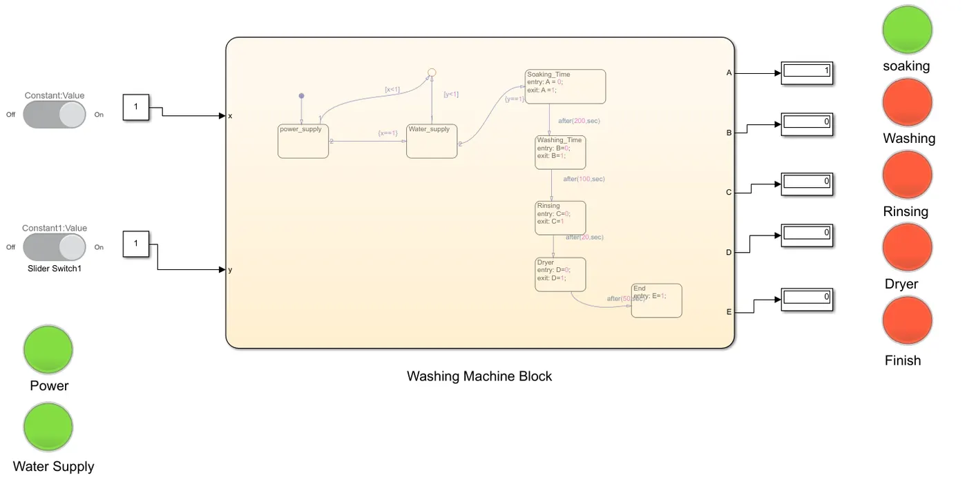
2. Here I have turned on both the power and the water supply. The simulation is made to run for 250 seconds. The result indicates that the washing process has started with the soaking process been completed (As in the question the soaking process is done for 200 seconds). Similarly based on the time allocation the simulation is made to run to achieve the rest of the process.
3. This is the final result, indicating that all the processes within the washing machine been carried out under the given initial conditions.
Theory: Case 2- Make a Simulink chart for the “Gear shift” logic.
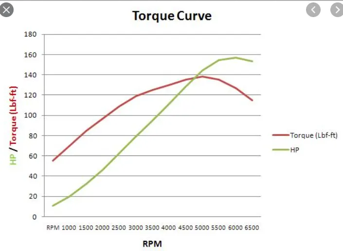
The gear shifting mechanism is kept inside the Transmission to provide the uniform torque towards the drive shaft. This is because the IC engine produces the optimum torque only after a certain speed and it drops again. So in order to achieve the optimum torque on a continuous basis Transmission is used, with this, we can manipulate the Torque with the help of "Gear ratio" (by using varied gear sizes inside)
Manual Transmission Gear:
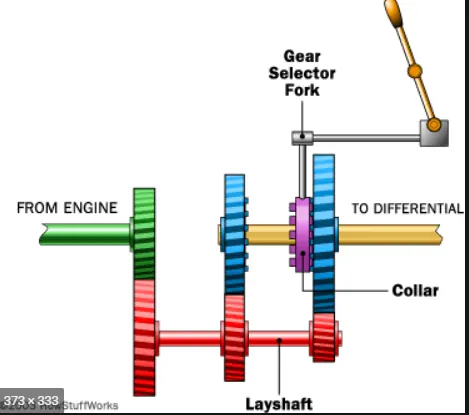
As shown in the above figure, Manual transmission has synchronous gears or continuously meshed gears are kept. (In Automatic Transmission Planetary gears are used) Based on the speed requirement the gear is shifted using the Gear knob, which in turn makes the collar gear to get meshed with the appropriate gears. The output shaft is connected to the collar gear, hence whichever gear gets meshed with the collar gear will be the output shaft.
During the gear shifting process, it is mandatory that the input shaft is disengaged from the engine. This is done with the help of the clutch plate (Torque convertor in case of the Automatic Transmission).
State Flow Chart: Case -2
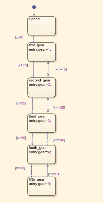
Here as per the question, the gears are arranged with the condition on the speed range. For example, Speed above 0 till 15 will fall under first gear and the chart is also designated in such a way to satisfy the condition.
Simulink Model: Case-1
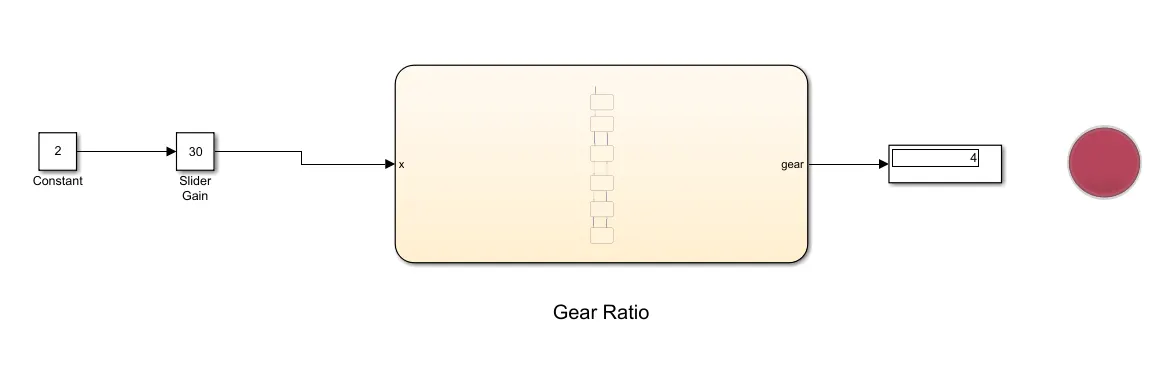
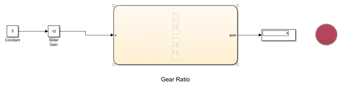
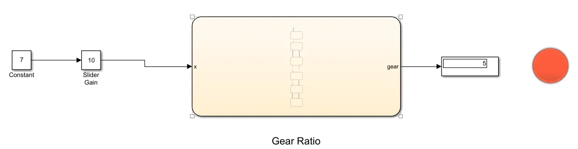
Here 2 input blocks are kept, one is the constant and the other is the "Slider Gain" Block. The Slider Gain block performs a scalar gain that you can modify during the simulation. The block supports fixed-point data types. The value given in the constant block get's multiplied with the Slider gain value during the simulation.
To determine the gear value required for the particular speed, a "Display" block is placed. The lamp is also placed whose parameters are set in a way that for each gear it will produce individual colors. The color inputs are shown below,

Results: Case 2
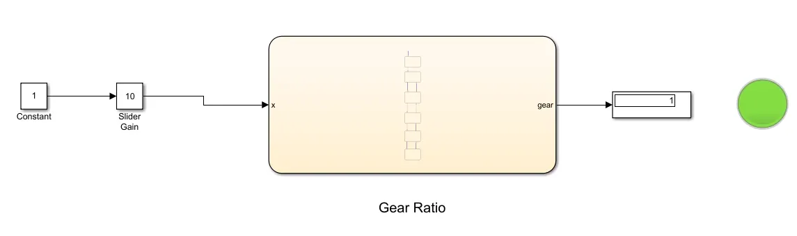
a) for the first gear, Speed is 10 kmph
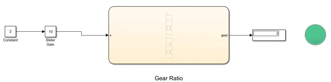
b) for the second gear, Speed is 20kmph
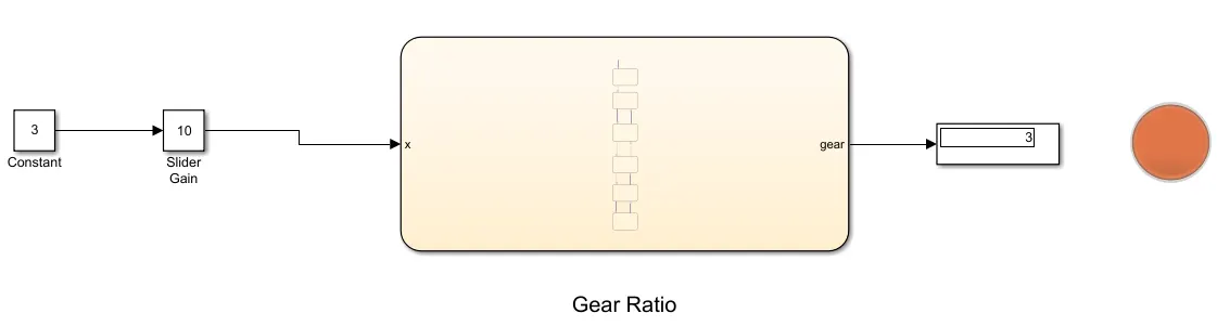
c) for the third gear, Speed is 30kmph
d) for the fourth gear, Speed is 50kmph
e) for the fifth gear, Speed is 70kmph
Models:
Washing machine:
https://drive.google.com/file/d/1iasZUPAxJEaC2bAmAc9Ywgejie8vjw5e/view?usp=sharing
Gear ratio:
https://drive.google.com/file/d/1YCKJsf1jXn3XCtr2uc9jXdmwfEijtEdk/view?usp=sharing