Week - 4
AIM -
- Implement control logic of washing machine using Stateflow by giving certain conditions as per power input & water As per this input, machine operates and obtain output by lamp light.
- Create the Stateflow for gear shift & vary the speed as input and obtain the output as gear number in
OBJECTIVE –
- To implement control logic of washing machine using Stateflow as per given
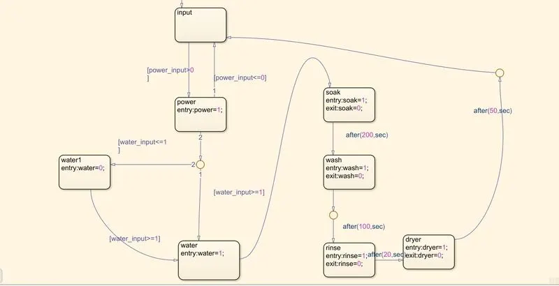
-If the power supply is available, the system gets activated.
-If the power supply is not available, stop the process and indicate through LED.
-Soaking time should be 200 seconds.
-The rinsing happens for next 20 seconds and dryer runs for next 50 seconds.
-After all the processes have completed turn ON the finished LED.
- Make a Simulink Chart for the Gear Shift Logic as per below conditions
Speed Range (kmph) Gear
0 to 15 1
16 to 25 2
26 to 40 3
41 to 60 4
61 above 5
Give speed input while the simulation is running and display the gear number.
Stateflow - Stateflow provides the graphical language that includes state transition diagrams, flow charts, state transition tables, & truth tables. It is used to describe how MATLAB algorithms and Simulink models react to input signals, events and time based conditions. Stateflow enables you to design and develop supervisory control, task, scheduling, fault management, communication protocols, user interface & hybrid systems. with stateflow, you model combinatorial & sequential decision logic that can be simulated as a block within a Simulink model or executed as an object in MATLAB. Graphical animation enables you to analyse & debug your logic while executing. Edit time & run time checks & ensures design consistency and completeness before implementation.
Control Logic – Control logic is a key part of a software program that controls the operations of the program. The control logic responds to commands from the user & it also acts on its own to perform automated tasks that have been structured into the program. Controlled logic can be modelled using a state diagram, which is a form of hierarchical state machine.
PART I – Control logic of a “washing machine” using Stateflow
A washing machine is a machine used to wash various types of clothes without applying any physical effort. With a washing machine, you don’t have to rub the clothes with your hand or squeeze them to remove the water from them. The washing machine is also called a clothes washer or simply a washer. The washing machine enables you to wash your clothes automatically without having to supervise its operation. All you have to do is put the clothes in the machine and select the wash mode. The washing machine automatically takes in the amount of water and detergent required and it also automatically sets the timer for washing, rinsing, and drying as per the selected mode and the number of clothes.
Stages of washing machine:
Let us now undergo the stages of a washing machine which in turn helps you to understand better and pick the option depending on the basis of your need successfully.
- Prewash
- Washing
- Rinsing
- Spinning
Learning these things essential to pick the right option at the right time.
Prewash
The option called prewash indicated filling the drum with a certain water level and mix up with the detergent powder. All this option helps to wash out all the stains including the stubborn or dirt very well from the clothes. This is possible as we soak the whole clothes placed into the drum. Finally, drain the water without making a second thought.
Taking the amount of water is different for both front load and top load washers respectively. In the front-load washing machines, it is all up to the settings done by the single user. Whereas at the top load washers, there are water level sensors for filling the drum at a certain level and clean the entire load getting rid of stubborn stains successfully.
Washing
At this particular time, the machine uses agitation which is for mixing both water and detergent, in turn moving the clothes all around the drum. Generally, the top load washing machines come with an agitator or impeller placed at the center of the tub.
While coming to front-load washers, it depends upon the rotation of the entire tub provided for enhancing better wash and cleaning the load ultimately. Moreover, the duration taken to complete the wash cycle is depends upon the settings option chosen by the user. Always the heavy load enhances high duration. Small or limited load enhances less duration.
Rinsing
The option called rinsing is known for the multi-talented option. During this particular cycle is on the flow, the soapy water taken from the clothes. And all the fresh or pure water is sparkled to the clothing available in the tub. This particular rinse option held responsible for taking soapy water out of the washer without facing any kind of difficulties. Finally, the agitation with plain water is considered the last step in the rinsing option.
Spinning
Spinning is done to dry the entire clothes before getting to the end of the actual wash cycle. And these several washing machines are going to be spun at different speeds. In turn, the speed of one particular spin is calculated in revolutions per minute (rpm) respectively. This indicates the speed of the spin extracting the whole amount of water from the clothes making it dry very well.
Modeling of Washing machine in Simulink:
these are the following things we need for modeling the subs system of washing machine logical block settings:
1. Toggle switch
2. Constant
3. State flow chart
4. Lamps
5. Display
Now following with steps involves in the process we go step by step:
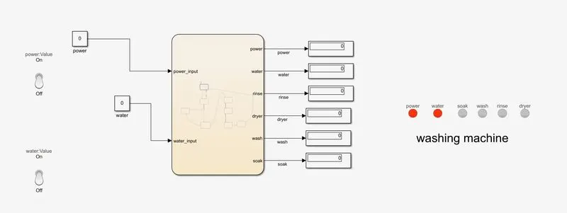
1. When both power and water is in off condition respective led shows red colour indicate power and water is not available
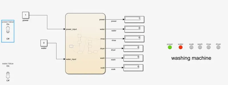
2. When Power ON but water supply not available led indicate with red colour
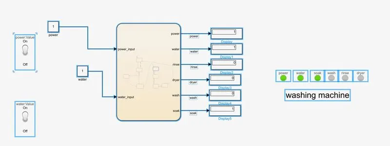
3. Both power and water supply ON machine starts its process soaking and led shows the indication.soking is for 200sec.
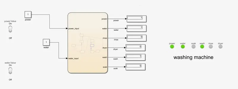
4. After 200 sec of soaking washing ON for 100sec
5. After washing process rinsing the clothes for 20sec in process
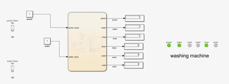
6. Drying processs starts after rinsing for 50 sec.
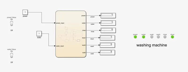
This is what it looks like in the State flow chart:
PART II – Implementation of Control Logic for Gear Shift Using State flow
STUDY 2 –
GEAR SHIFT
A manual transmission also known as a manual gearbox a standard transmission or colloquially in some countries as a stick shift is a type of transmission used in motor vehicle applications. It uses driver operated clutch, usually engaged or disengaged by a foot pedal or hand lever for regulating torque transfer from the engine to the transmission and the gear selector can be operated by hand.
A conventional 4 or 5 speed manual transmission is often the standard equipment in a modern based model vehicle with 4 speed being more common in non-passenger vehicles such as pickup trucks and light commercial vehicle & higher end vehicles such as sport cars and luxury cars are often ususally equipped with 6 speed transmission for base model.
Gearbox is the second element in the powertrain in an automobile. It is used to change the speed and torque of vehicles according to the variety of road and load conditions. The transmission box changes the engine speed into torque when climbing heels and as per requirement of the vehicle & hence it is also known as torque converter.
Following are the functions of the gearbox-
- Provide the torque needed to move the vehicle under the variety of road and load conditions and doing this by changing the gear ratio between engine crankshaft and vehicle drive
- To provide assistance to shift backwards/ reverse so that vehicle moves in that
- To help the vehicle to shift into neutral for starting the
Working – In a gearbox the tertiary counter shaft counter shaft is mashed to the clutch with the use of couple of gears so the countershaft is always in running condition. When the tertiary shaft is brought in contact with the main shaft by the use of meshing gears the main shaft starts to rotate according to the gear ratio. When thhe driver wants to change the gear he simply press the clutch pedal which disconnects the tertiary shaft with the engine and connects the main shaft with the tertiary shaft by another gear ratio by the use of gearshift lever.
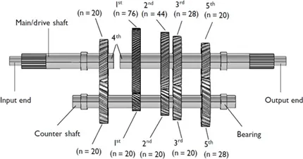
STEPWISE PROCEDURE:
- Create a chart block for defining the stateflow as per the given
- If speed is less than or equal to 0, the flow is terminated and gear 0 is at the junction else 1 is carry forwarded.
- If speed is greater than 0 and less than or equal to 15, the flow is terminated and gear 1 is
- If speed is greater than 15 and less than or equal to 25, the flow is terminated and gear 2 is
- speed is greater than 25 and less than or equal to 40, the flow is terminated and gear 3 is
- speed is greater than 40 and less than or equal to 60, the flow is terminated and gear 4 is
- speed is greater than 60, the flow is terminated and gear 5 is
Control Logic Structure:
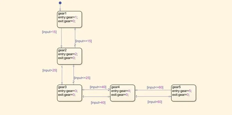
In the above logic control first - the default transition is dragged from the browser menu.
Five gear state is created with the state condition of Gear (G) 1,2,3,4,5 respectively and their transition is connected with speed range condition as shown in the image.
The transition conditions for gear shift is decided as speed > 15 shift to G = 2
speed > 25 shift to G = 3
Speed > 40 shift to G = 4
Speed > 60 shift G = 5 ( When the speed is increasing from 0 – 60 kmph)
Similarly in reverse direction Speed < 60 shift to G = 4
Speed <40 shift to G =3
Speed < 25 Shift to G = 2
Speed < 15 Shift to G = 1 ( when the speed is decreasing from 60 -0 kmph)
Results:
After event creation flow chart is generated using some blocks from the library and their connections are done as mentioned below –
A constant block is connected with slider gain block to provide initial input.
Slider gain block is used to define the speed slider to change the speed during simulation is running and it acts as input for speed.
The output port GEAR is connected with the Display to indicate the current gear for current speed in the slider gain.
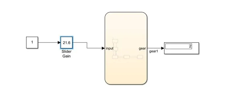
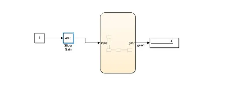
When the run time is kept as an infinite and slider is made to slide for the speed then we can see the gear number as 2 for speed 21.5 and gear number as 4 for speed 49.6
By changing the slider position the display value will change simultaneously.