Week -2
PART:1
AIM:
To Make a Simulink model of Doorbell using solenoid block.
Blocks used in doorbell simulink:
solenoid:
A solenoid is a type of electromagnet, the purpose of which is to generate a controlled magnetic field through a coil wound into a tightly packed helix.The coil can be arranged to produce a uniform magnetic field in a volume of space when an electric current is passed through it. The term solenoid was coined in 1823 by André-Marie Ampère to designate a helical coil.In engineering, the term may also refer to a variety of transducer devices that convert energy into linear motion.In simple terms, a solenoid converts electrical energy into mechanical work.
Battery:
his block models a battery. If you select Infinite for the Battery charge capacity parameter, the block models the battery as a series internal resistance and a constant voltage source. If you select Finite for the Battery charge capacity parameter, the block models the battery as a series internal resistance plus a charge-dependent voltage source defined by:
V = Vnom*SOC/(1-beta*(1-SOC))
where SOC is the state of charge and Vnom is the nominal voltage. Coefficient beta is calculated to satisfy a user-defined data point [AH1,V1].
Switch :
The block represents a switch controlled by an external physical signal. If the external physical signal PS is greater than the threshold, then the switch is closed, otherwise the switch is open.
Pulse Generator :
The Pulse Generator block generates square wave pulses at regular intervals. The block waveform parameters, Amplitude, Pulse Width, Period, and Phase delay, determine the shape of the output waveform
Ideal Translational Sensor :
The Ideal Translational Motion Sensor block represents a device that converts an across variable measured between two mechanical translational nodes into a control signal proportional to velocity or position. You can specify the initial position (offset) as a block parameter.The sensor is ideal since it does not account for inertia, friction, delays, energy consumption, and so on.Connections R and C are mechanical translational conserving ports that connect the block to the nodes whose motion is being monitored. Connections V and P are physical signal output ports for velocity and position, respectively.The block positive direction is from port R to port C. This means that the velocity is measured as v = vR – vC, where vR, vC are the absolute velocities at ports R and C, respectively.
Electrical Reference:
The Electrical Reference block represents an electrical ground. Electrical conserving ports of all the blocks that are directly connected to ground must be connected to an Electrical Reference block. A model with electrical elements must contain at least one Electrical Reference block.
Scope :
This block is used to display signals during simulation.
Mechanical Translational Reference :
This block represents a mechanical translational reference point, that is, a frame or a ground. Use it to connect mechanical translational ports that are rigidly affixed to the frame (ground).
Simulink-PS converter :
Converts the Simulink input signal to a Physical Signal.
PS-Simulink Converter :
Converts the input Physical Signal to a Simulink output signal.
Solver configuration:
Each physical network represented by a connected Simscape™ block diagram requires solver settings information for simulation. The Solver Configuration block specifies the solver parameters that your model needs before you can begin simulation. Each topologically distinct Simscape block diagram requires exactly one Solver Configuration block to be connected to it.
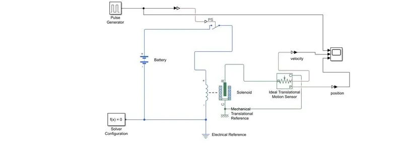
Simulink Model : Doorbell circuit using Solenoid block
Scope Result:
Observation from the result:
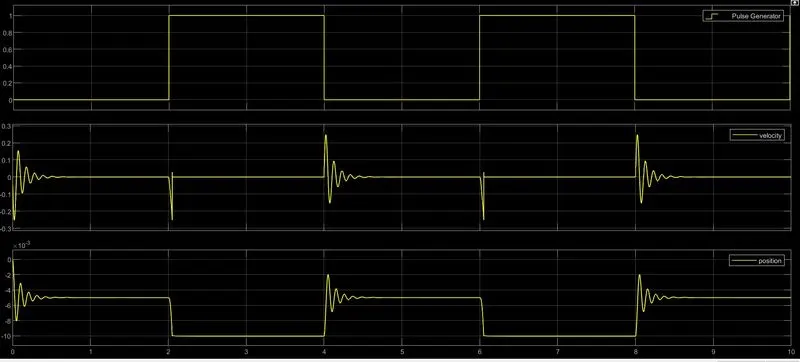
In the above doorbell simulink model solenoid door bell is powered with 12v battery.The input signal is given from pulse generator through ps switch.In the pulse generator at the time interval of 4sec with delay time of 2 sec with 50% pulse with period at amplitude of 1 given.If the given signal is greater than the threshold value then the switch will on.when the switch on, the plunger of the solenoid coil that is port R move towards port C .The position and velocity of the plunger is observed through scope. From the scope it is clear that when the switch is on the position of the plunger moves -10 mm from its intial value. And the force of the of the plunger is 0.25N. When the switch is in off condition the position of the plunger is move back to its orginal position and the force of the plunger is also 0.25N But this time it is in a opposite direction.when ever the plunger movement occurs there is a vibration occurs.it is clearly visible from the scope results.To control the vibrations of the plunger we can adjust the stiffness and damping co efficient of the plunger in the solenoid block.
PART:2
AIM:
To make a Simulink Model Using a thermistor to sense the temperature of a heater & turn on or turn off the fan as per the below conditions:
Temperature source: 20 °C from 0 to 10 seconds, 27 °C from 10 to 30 seconds, 23 °C from 30 to 50 seconds
Fan conditions: ON if the temperature above 25 °C, OFF otherwise
THERMISTOR:
A thermistor is a type of resistor whose resistance is dependent on temperature, more so than in standard resistors. The word is a combination of thermal and resistor. Thermistors are widely used as inrush current limiters, temperature sensors (negative temperature coefficient or NTC type typically), self-resetting overcurrent protectors, and self-regulating heating elements (positive temperature coefficient or PTC type typically).
Thermistors are of two opposite fundamental types:
- With NTC thermistors, resistance decreases as temperature rises. An NTC is commonly used as a temperature sensor, or in series with a circuit as an inrush current limiter.
- With PTC thermistors, resistance increases as temperature rises. PTC thermistors are commonly installed in series with a circuit, and used to protect against overcurrent conditions, as resettable fuses.
Blocks used in simulink:
- NTC Thermistor block
- Battery
- Electrical reference
- Resistor
- Voltage sensor
- Controlled temperature source
- Signal builder block
- PS-simulink converter
- Simulink-PS converter
- Scope
- Switch
- Constant block
- Dc motor
- Controlled voltage source
- Mechanical rotational reference
- Mechanical rotational sensor
- Solver configuration
Simulink model:
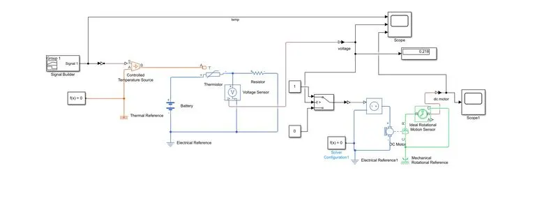
In the above simulink model NTC thermistor block is connected with battery source and resistor with electrical reference . To measure the voltage across the circuit voltage sensor is connected across it.Controlled temp source in controlled by signal builder block with thermal reference. In the signal builder block as per condition given signal to be generante i.e At 0-10 sec 293k,10-30sec 300k,30-50sec 297k. The generated signal are in kelvin. B Port of the controlled voltage source is connected to the A Port of the thermistor block. The input to the switch is fed from the voltage sensor. In the switch if the threshold voltage is >port 1 then the output is from port 1 otherwise output is from port 2. The output of the switch to fed the controlled voltage source to switch on and off the fan (here the fan is dc motor) as per condition given.
Scope Result:
Observation from the result:
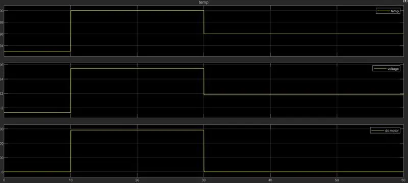
From the scope result it is seen that when the temperature is at 20degree till 0-10 sec the voltage measured in the voltage sensor is 0.2v which is less thsn the threshold voltage so the switch is in off condition due to that the fan is in off condition. But when the temp shoots up to 27degree at 10-30 sec due to negative temp co-efficient thermistor whenever temp increases the ressistance will decrease. It will help the current along with voltage to flow in the ciruit. so measured voltage in the voltage sensor is exceed the threshold voltage (i.e 0.25v)due to this switch will turn on. This will allow the fan to rotate when temp reach above 25 degree. when the temp decreases to to 23 degree at 30-50 sec due to negative temp co-efficient resistance value increases so the voltage drops to below the threshold value. Due to this switch will go to off condition which turn off the fan.