Project - Speed Control of a Direct Current (DC) motor
AIM:
In this project, a Simulink model for the DC motor will be first developed per the schematic shown in Figure 1.
Use the Proportional, Integral, and Derivative (PID) control design knowledge gained in the training to design, develop and test a controller to maintain a desired speed for the motor.
BLOCKS USED IN SIMULINK MODEL:
- GAIN
- ADD
- INTEGRATOR
- SCOPE
- STEP
- TRANSFER FUNCTION
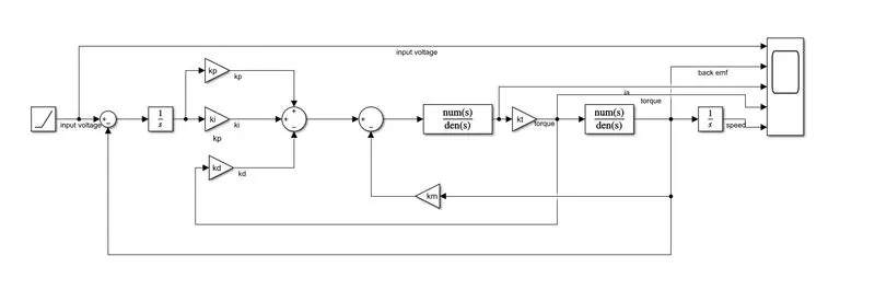
BELOW ARE THE SIMULINK MODEL OF A DC MACHINE:
- Input supply is fed by using step block
- It is subract with back emf and the error is given to pid contrller
- In the pid controller propotional gain kp,derivative gain kd,integral gain ki is present.It will track the steady state error, overshoot,under shoot and give the output according to it to the dc machine
- Then it is given to the armature of the dc machine and the output torque is measured by multiplying torque constant ta.
- It is given to the another transfer function block moment of inertia J and multiply with friction co efff to get the final output which is speeed of the dc machine
%parameters of dc motor design
j=0.01;%inertia
bf=0.1; %friction
km=001; %back emf
kt=0.01 %torque
ra=1 %armature resistance
la=0.5 %inductance
%design of pid controller
a=[-bf/j kt/j; -km/la -ra/la];
b=[0;1/la];
%placement of poles
wn=6.28;
z=0.5;
p1= -z*wn+wn*sqrt(z^2-1)
p2= -z*wn-wn*sqrt(z^2-1)
P=[p1;p2]
K=place(a,b,P)
kp=K(1);
kd=K(2);
ki=2500;
s=tf('s');
G=wn^2/(s^2+2*zeta*wn*s+wn^2);
pzmap(G,'r');grid on;
Below are the scope results of the dc machine parameters
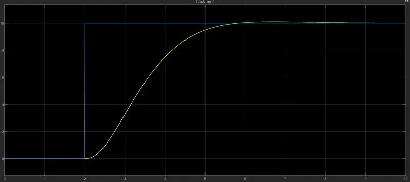
In the above results the given reference signal which is in blue line get response at t=2sec at the moment pid controller output signal also try to catch the reference signal.by tuning the integral gain properly there is overshoot and under shoot is present.
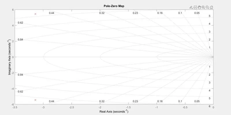
Below are the pole placement of dc machine.both the poles are in left half plane which shows the above system is stable.