Week - 4
~Objective:--
- Implement control logic of a “washing machine” using Stateflow as per given sequence:
- If the power supply is available, the system gets activated
- If the Water supply is not available, stop the process & indicate through LED
- Soaking time should be 200s followed by Washing time of 100s.
- Then rinsing happens for next 20s & dryer runs for 50s
After all the processes have completed turn on the finished LED
~First we will see a working pronciple of automatic washing machine
Automatic washing machines work on a very simple principle they agitate clothes rapidly in soapy water until they're clean and then clean water replaces the soapy water until the clothes are rinsed completely. This process removed all the stains and dirt from the clothes, making them clean
~Basically Automatic Washing machine has following steps
- Power Supply
- Water intake
- Soaking
- Washing
- Rinsing
- Drying
- End
~Now we will go through each step
- Power Supply:--
Power supply is nothing but suppling the power to the machine so that it can perform the task,Without the power supply/Current the machines can not run It is the most important step to run the washing machine
- Water intake:--
Here in this step the water Flows through the Washing drum automatically depending upon the load capacity of the machine it is also an important step in washing clothes if the water is not supplied to the machine then the machine stops working and gives an error
- Soaking:--
Soak Function is used to dip clothes in detergent water to remove dirt from the clothes. In this function customer need to select soak from a panel. Soak - This function is available with wash timer, In 42 min of washing 27 min is soak and 15 min machine will wash the clothes.
- Washing:--
Your washing machine is filled with water according to the selected load size, then the clothes and soap are swirled around together, Rinse: The dirty, soapy water is drained, then the washing machine is refilled and your clothes are "rewashed" in clean water.
- Rinsing:--
The dirty, soapy water is drained, then the washing machine is refilled and your clothes are "rewashed" in clean water. Spin: All the water is drained completely, then your clothes are spun very fast and excess water is removed thanks to centrifugal force
- Drying:--
The washing machine's dry function is to reduce or eliminate the drying time by heating the inside of the washing machine,and it drys the cloths
~There are two types of automatic washing machines:-
- Fully automatic washing machine:--
fully automatic washing machines clean & dry the clothes in only one tub.
- semi automatic washing maschine :--
Semi-automatic washing machines are the ones that have two separate tubs to clean and dry the clothes respectively
- In Fully automatic washing machine:--
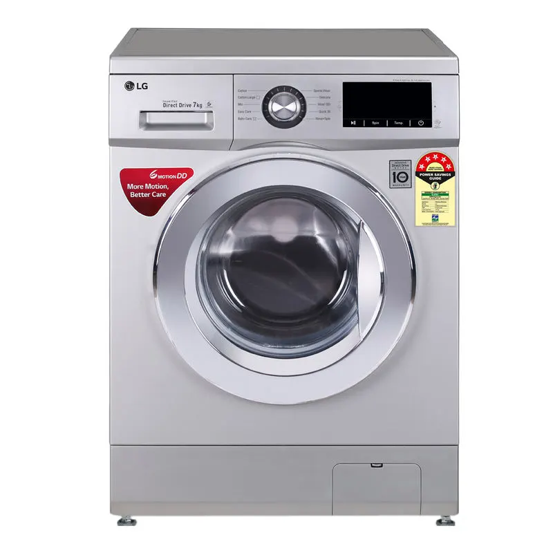
1,Front Load :--
Front Load is nothing but the drum will be in front side of the machine and it is shown in the below figure
2,Top Load:--
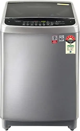
In top load the drum will be on top and the lid to add the cloths will be placed upwards and the figure is shown below
Implement control logic of a “washing machine” using Stateflow as per given sequence:
- If the power supply is available, the system gets activated
- If the Water supply is not available, stop the process & indicate through LED
- Soaking time should be 200s followed by Washing time of 100s.
- Then rinsing happens for next 20s & dryer runs for 50s
After all the processes have completed turn on the finished LED
~Modeling of Washing machine in Simulink:
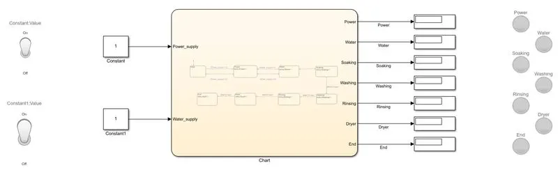
these are the following things we need for modeling the subs system of washing machine logical block settings:
1. Toggle switch
2. Constant
3. State flow chart
4. Lamps
5. Display
~Input:--
~Now following are the steps involves in the process to control logic of a “washing machine” using Stateflow:--
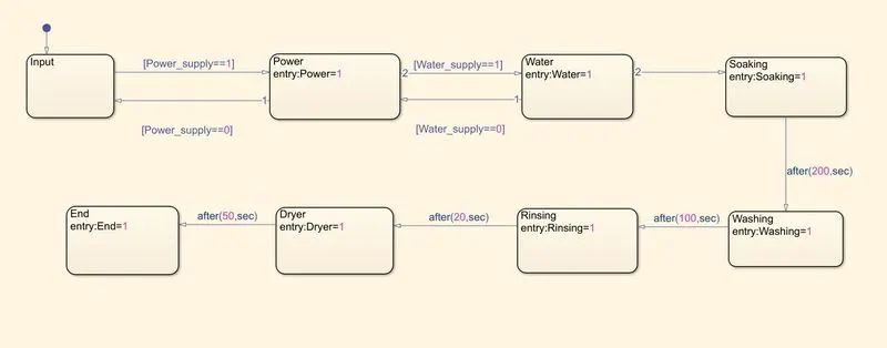
1. Switced OFF when non opertaional:--
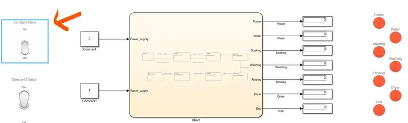
When the power supply is turned off , the system gets diactivated
2. Power ON:--
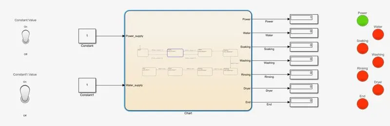 If
If
The power supply is available, the system gets activated
3. Water Supply ON:--
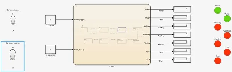 f
f
The Water supply is available, when the water supply switch is onn and the process & indicate through LED
4. Water Supply OFF:--
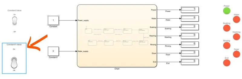
The Water supply is not available, stop the process & indicate through LED and the the working stops
5.Soaking:--
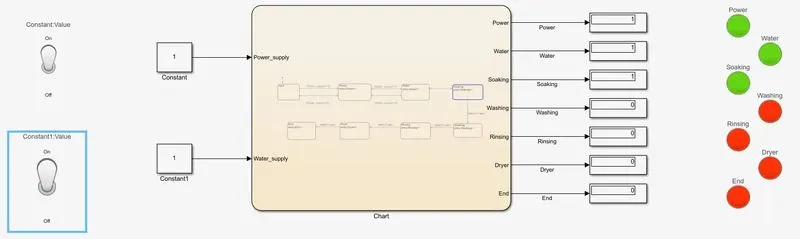
Soaking time should be 200s
6.Washing:--
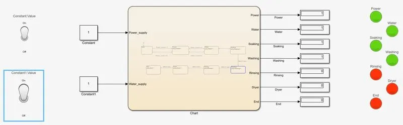
Washing time is of 100s.
7. Rinsing:--
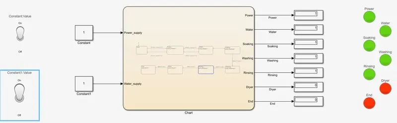
Then rinsing happens for next 20s
8.Drying:--
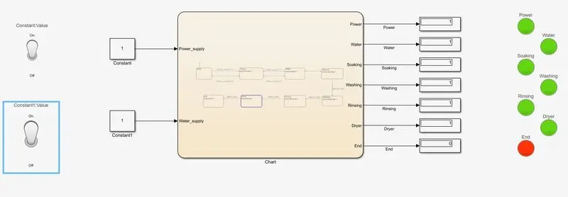
dryer runs for 50s
9.END process:--
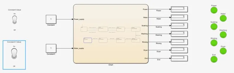
And the procces is ended After all the processes have completed turn on the finished LED
~The State Flow Chart is as shown below :--
~Result:--
Implemented control logic of a “washing machine” using Stateflow as per given sequence:
The power supply is available, the system gets activated
The Water supply is not available, stop the process & indicated through LED
Soaking time should be 200s
and followed by Washing time of 100s.
Then rinsing happens for next 20s & dryer runs for 50s
~Drive link for the Washing machine model:--
https://drive.google.com/drive/folders/1N8Gzb5qKjuU3wDtffMihGRWF4BUiFp2B?usp=sharing
~Objective:--
Make a Simulink chart for the “Gear shift” logic as per below conditions:
Speed Range(kmph) Gear
0 to 15 1
16 to 25 2
26 to 40 3
41 to 60 4
Above 61 5
Give speed input while the simulation is running & display the gear number.
~Gear Shifting :--
The term gear stick mostly refers to the shift lever of a manual transmission, while in an automatic transmission, a similar lever is known as a gear selector. A gear stick will normally be used to change gear whilst depressing the clutch pedal with the left foot to disengage the engine from the drivetrain and wheels.
The term gear stick mostly refers to the shift lever of a manual transmission, while in an automatic transmission, a similar lever is known as a gear selector. A gear stick will normally be used to change gear whilst depressing the clutch pedal with the left foot to disengage the engine from the drivetrain and wheels.
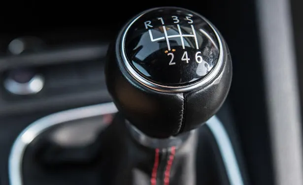
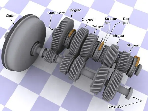
A gear shift mechanism for a manual transmission includes a shaft axially movable for selecting shift planes and rotatable for engaging the gears defining the shift planes. The shaft is held in a reference shift plane by two helical springs.Generally, you want to shift gears when your car reaches 2,500-3,000 RPM.
- Depress the clutch.
- Move the shifter up to the next highest gear.
- Release the clutch while pressing down on the gas.
~Basically there are three types of transmissions
1,Manual Transmission
2,Automatic Transmission
3,Semi Automatic Transmission
~These are the following block setup did we need for the setup:
1. State flow chart
2. Slider
3.Constant
4. Display
5. lamps
6. Slider Block
and the output is displayed on the display block.
~Input:--
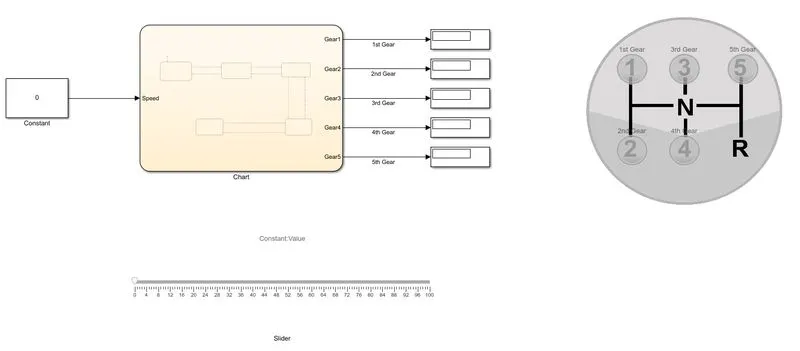
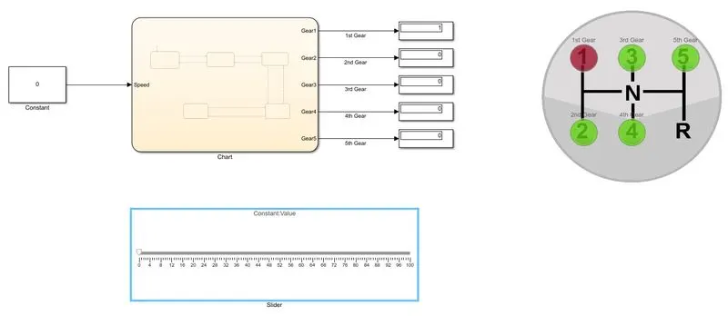
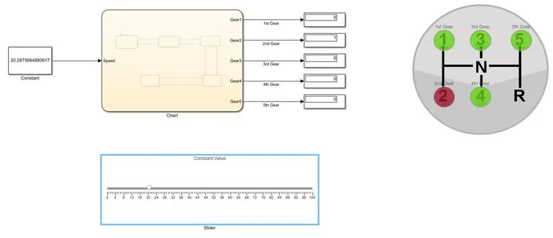
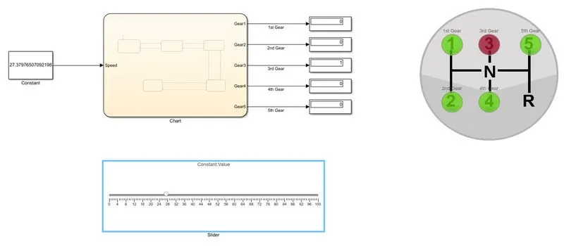
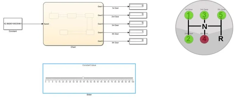
When the speed range is from 41 to 60 the Gear should be in the Fourth gear and it is shown in the above figure and it is in red color and we have to set the speed from the slider block.
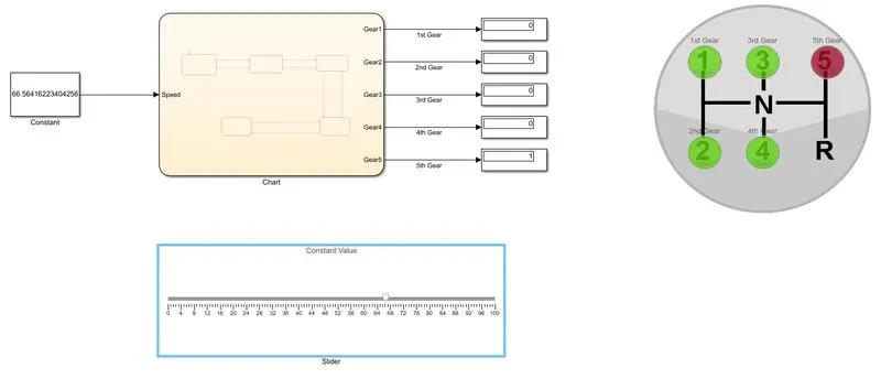
When the speed range is from 61 and above the Gear should be in the Fifth gear and it is shown in the above figure and it is in red color and we have to set the speed from the slider block.
~The Simulink chart for the “Gear shift” is shown below:--
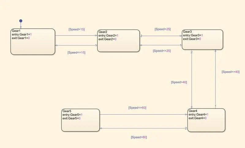
Speed Range(kmph) Gear
0 to 15 1
16 to 25 2
26 to 40 3
41 to 60 4
Above 61 5
and the speed input is also given while the simulation is running & display the gear number.
~Drive Link for the model:--