Week - 4
1. Implement control logic of a “washing machine” using Stateflow as per given sequence:
- If the power supply is available, the system gets activated
- If the Water supply is not available, stop the process & indicate through LED
- Soaking time should be 200s followed by Washing time of 100s.
- Then rinsing happens for next 20s & dryer runs for 50s
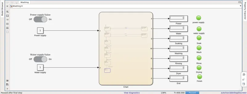
After all the processes have completed turn on the finished LED
Solution: Washing machine process is electrcially controlled which is used mechanically in order to wash the clothes using drum, valves, pump, motor and heating. The valve opens and the dirty water is drained out of the drums used for washing and rinsing, spining the clothes. There are 4 processes in order for the clothes to clean namely:
Soaking: In this first step the clothes are put in the drum and dipped in the water (run by valves) and left for soaking in order for the dirt to soften.
Washing: In the washing process, drum turns around and work as an agitator, moving clothes through the wate. After the wash is finished, the pump drains the water from outer drum.
Rinsing: The soap water filled with dirt is drained and machine tub is refilled and clothes rewashed with clean water. Once this is done the water is fully drained and clothes are spun really fast to remove the excess water using centrifugal force.
Drying: During this process the warm air is pushed through the wet clothes in machine to extract the moisture and pumped down the drain. Air is reheated and the cycle repeats until the clothes are warm and dry.
To represent the working of Washing machine in simulink we make use of stateflow and represnt it using a finite step algorithm.
Inputs are givng to the chart as power supply and water supply. Flow chart works as per the given sequence of processes of machine.
Blocks used
Constant Block - These are used to provide the on/off to the two inputs i.e. water supply and power supply.
Flow chart - This blocks holds the whole algorithm in form of a flow chart defining the machine working with all the processes in a finite time cycle.
Display Block - This displays the value 1 for when the process is completed.
Lamps - These are used to inicate the how the process is working. As each process completes the lamps turn green indicating the process has been completed.
Below are the processes as shown:
If the power supply is available, the system gets activated.
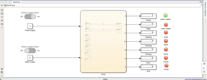
If the Water supply is not available, stop the process & indicate through LED
Both power supply and water supply are given
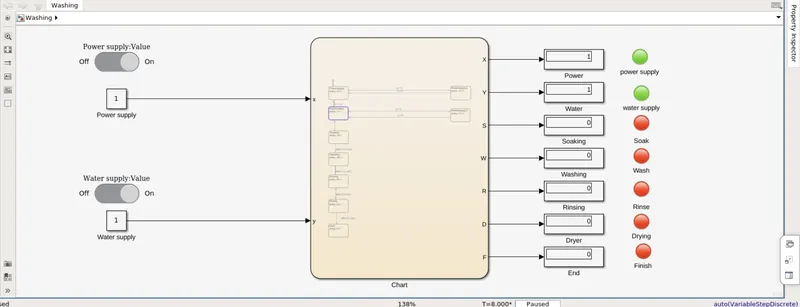
Soaking time should be 200s followed by Washing time of 100s.
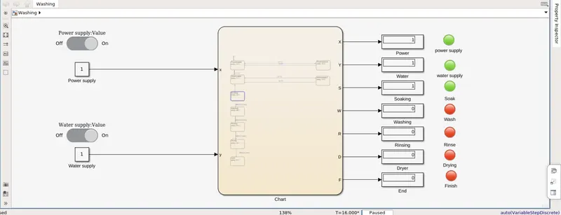
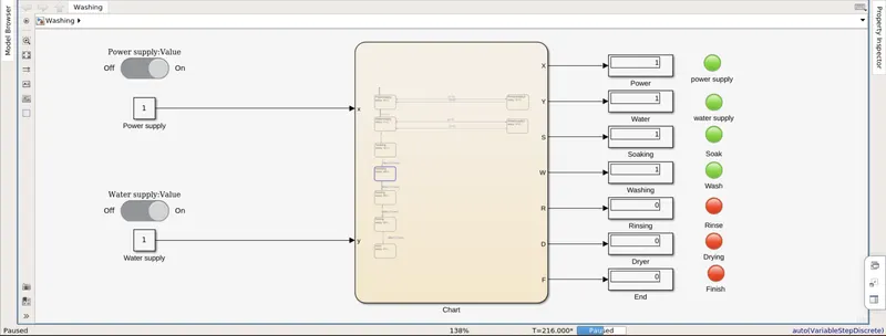
Then rinsing happens for next 20s & dryer runs for 50s
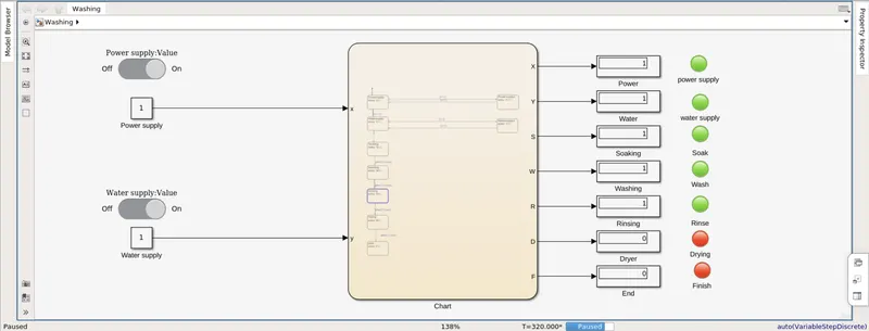
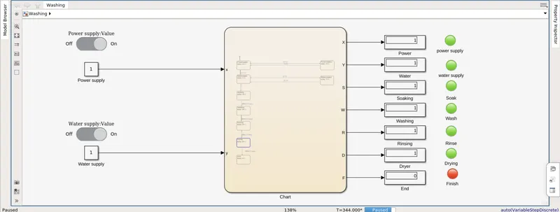
After all the processes have completed turn on the finished LED
2. Make a Simulink chart for the “Gear shift” logic as per below conditions:
Speed Range(kmph) Gear
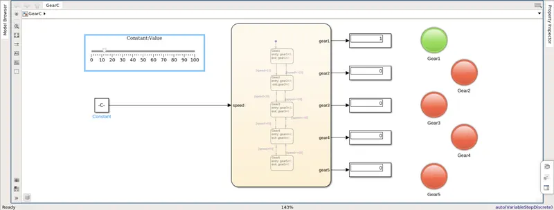
0 to 15 1
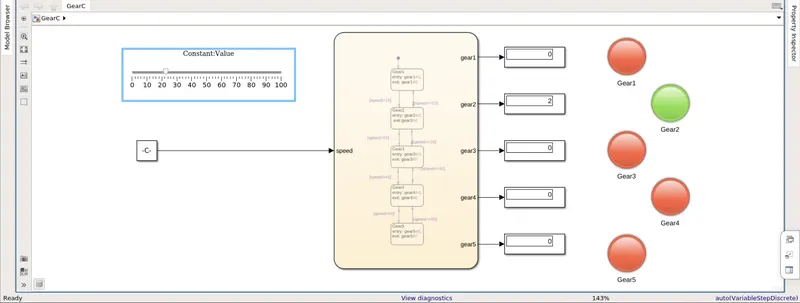
16 to 25 2
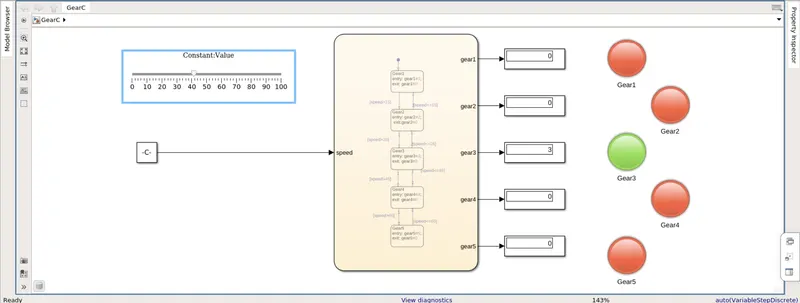
26 to 40 3
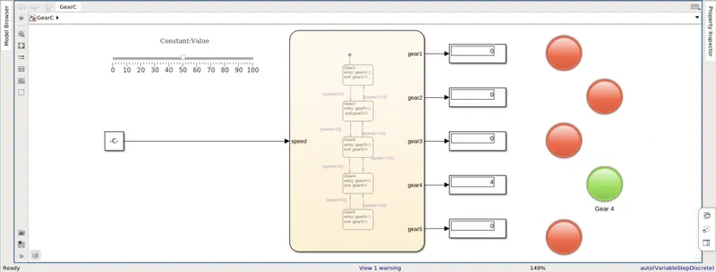
41 to 60 4
Above 61 5
Give speed input while the simulation is running & display the gear number.
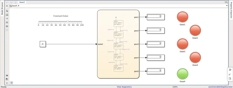
Solution: The simulink chart for the Gear shift logic will require the folowing blocks:
Constant - This block is use to povide the speed input via slider block to the state flow chart.
Slider - This block from dashboard helps in selecting the variable input and is linked to the constant block to provide input to state flow chart as speed.
State Flow Chart - This chart contains the gear shift algorithm in terms of a flow chart.
Display block - This displays the value of the gear which appears w.r.t input speed provided.
Lamps - These lamps are connected to each gear output and turn green according to which gear is being used.
0 to 15 1
16 to 25 2
26 to 40 3
41 to 60 4
Above 61 5