Project
AIM: To carry out the system level simulation of BAJA All Terrain Vehicle Model.
OBECTIVE: To prepare technical report explaining the model wherein the function of the main components of the model are explained along with the various case studies of the ATV model with CVT such as :-
- Open loop BAJA ATV Model with CVT
- Open loop BAJA ATV model with CVT using Dashboard
- Closed loop BAJA ATV Model with CVT
- Closed loop BAJA ATV model with CVT using Dashboard
THEORY AND BLOCKS USED:
All Terrain Vehicle is a single seater, 3-4 wheeler motorised vehicle which can run on all kinds of on-road and off-road conditions and terrains. Basically it is a small motor vehicle with three or four low-pressure tires designed for its feasibilty to run on any kind of terrain. Vehicle usually is built with a rigid structure and determined to have good performance in acceleration during hill/steep climbs. CVT is different from a conventional vehicle as they dont have gears and instead use pair of variable-diameter, cone-shaped pulleys connected by a rotating belt system.
ATV consists of following parts namely:
Input Blocks - Throttle, Brake, CVT Gear Ratio
Generic Engine - Engine sensor, Simple Gear
CVT - Variable transmissions, Inertia for rotating parts
Vehicle Body - Physical body, Tires, Shoe Breaks
Let us explore the models of ATV with CVT and explain different blocks being used that makes up the base of the model.
CASE 1 - Open loop BAJA ATV Model with CVT
A Simulink model for the open loop BAJA ATV model using CVT is shown below:
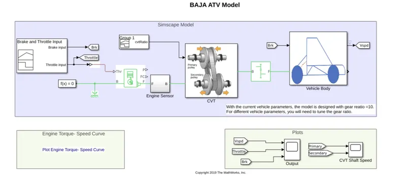
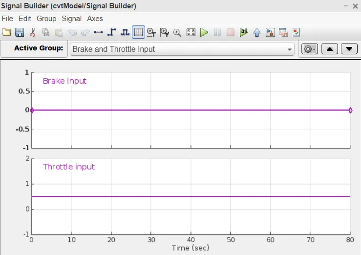
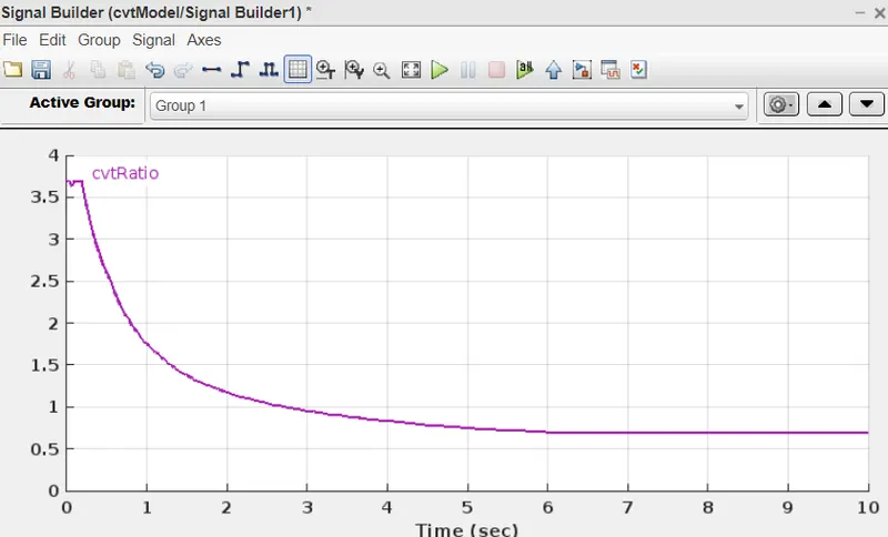
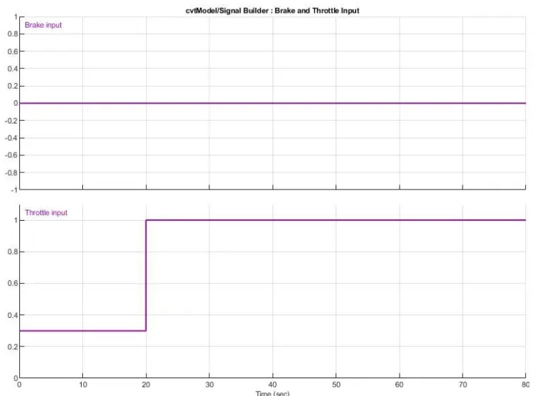
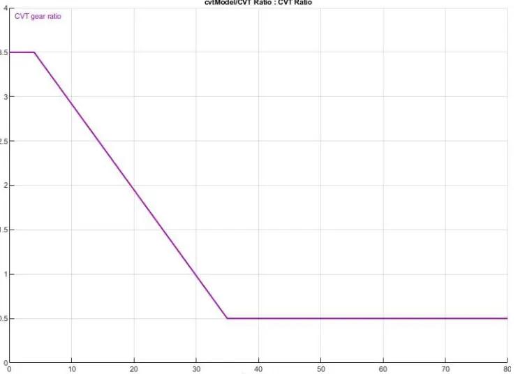
Signal Builder : The signal builder blocks helps to create signal sources in form of waveform which can be linear/non-linear and further use them in the model. Here in the BAJA model three input signal builder blocks are used- brake, throttle and CVT gear ratio.
Generic Engine: Generic engine in this model is the representation of the general Internal combustion engine. Types of engine include here are Spark-ignition type and diesel ignition type. Input can be given either from throttle or as torque. Throttle input must lie between 0 and one and specify torque demanded from engine as fraction of maximum possible torque, whereas while giving torque input it must lie between zero and maximum torque value.
If the speed determined for tyhe engine falls below the sum of stall speed threshold and stall speed the engine torque falls to zero whereas if engine speed exceeds the maximum speed, the simulation stops and generates and error message.
F and B connections are mechanical rotational conserving ports associated with the engine crankshaft and engine block respectively.
P and FC connections are physical signal output ports via which engine power and consumption is reported for the model.
Settings:
Input type: Normalized Throttle
Speed and torque vector are used as assigned parameters
Stall speed threshold: 100 rpm
Engine Intertia: 1 kg*m^2
Initial Velocity: 2100 rpm
No need to enter any fuel consumption model or speed control model for now.
Engine sensor: Engine sensor block is Ideal Rotational Motion sensor which measures angular velocity. It is an ideal sensor as doe not account for inertia, friction, delays, energy consumption,etc.
R and C are mechanical rotational conserving ports and connections W and A are physical signal output ports for velocity and angular displacement respectively.
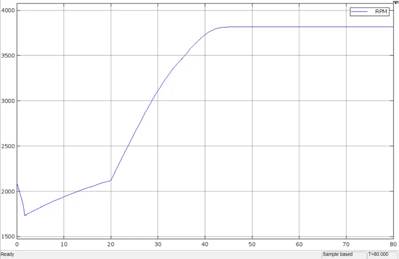
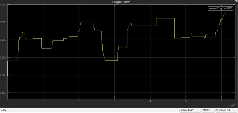
Engine speed output/Engine rpm
Simple Gear: This block represents the fixed ratio gear box i.e. it constrains the connected driveline axes of the base gear,B and follower gear, F, to rotate simultaneously with the specified fixed ratio.
We can include Meshing losses, Backlash and Viscous losses as well. Port B(base) and F(follower) are mechanical rotational conserving ports. Specifies the relation between B and F rotation directions with the output shaft rotates parameter. If we want to, optionally we can include thermal effects and expose thermal conserving port H by seeting friction model to temperature dependent setting.
Setting:
F to B Teeth ratio (NF/NB): 4
CVT (Continuously Variable Transmission) Subsystem:
CVT basically uses automatic transmission by changing a continuous range of gear ratios in CVT with a controlling enginre to work at a constant RPM while the vehicle moves at varying speed.
Inertia Blocks: This block is the ideal mechanical rotational inertia block. The input shaft inertia is represented by primary pulley and output shaft inertia is is represented by secondary pulley. The block positive direction is from the port to the reference point which means that the inertia torque will be positive if inertia is accelerated in positive direction.
Variable Ratio Gear: This block represents Variable Ratio gearbox which is used by mechanical belt CVT. The r is the physical input signal which defines the ratio of input to output angular shaft velocities. Port B(base) and F(follower) are mechanical rotational conserving ports. Specifies the relation between B and F rotation directions with the output shaft rotates parameter.
Further, two rotational motion sensor blocks are used for primary and secondary pulleys as well to track the angular velocities of both the pulleys.
Vehicle Body Subsystem
Vehicle body consists of two-axle vehicle body in longitudinal motion. This block has body mass, aerodynamic drag, road incline and weight distribution between axles due to acceleration and road profile. It has same/different numbers of wheels on each axle. It also includes pitch and suspension dynamics/variable mass and inertia. The vehicle doesnot move vertically relative to ground.
H port is mechanical translation conserving port associated with horizontal motion of vehicle body. V, NF, NR are physical signal output ports for vehicle velocity and front & rear normal wheel forces respectively. Physical signal port CG and M are exposed when the variable mass is modeled. M represents additional mass whereas CG uses a two element vector representing x and y distance offsets from vehicle CG to additional load mass CM. Physical signal port J accepts inertia of the additional mass about its own CG.
Setting:
Mass - 250 Kg
No. of wheels per axle - 2
Horizontal distance from GC to front axle - 1m
Horizontal distance from GC to rear axle - 0.35m
CG height above ground - 0.7m
Gravitational acceleration - 9.81 m/s^2
Tire: This block shows the rigid wheel tire combination in contact with the road and subject to slip. When torque is applied to the wheel axle, tire pushes on ground and transfers the resulting reaction as a force back on wheel. N is Normal force, S is slip, A is axle, H is hub.
Double Shoe Brake: This block provides high braking torque with small actuator deflections in application that include motor vehicles and some heavy machinery. The model employs a simple parametrization with accessible brake geometry and friction parameters.
Working Process of the Blocks in the Model
1.) The Signal Builder block mainly provides Brake and Throttle input and the CVT gear ratio to the system. The throttle output is further connected to generic engine block and output of the CVT gear ratio is given as input to CVT Block.
2.) From Generic engine output is provided to Engine sensor and output of engine sensor is further provided as input to CVT Block.
3.) Now CVT Block has inputs from CVT gear ratio and enegine parameters from engine sensors. In order to transfer CVT power to wheels , simple gear block is used in between them.
4.)The power output coming out of Simple gear block is given as input to the vehicle body block, which help us to check the values of throttling and braking effect and displayed on the scope for each effect.
5.)GoTo and From block connected to output of vehicle body block and scope respectively are used to display the performance curve when brake and throttle input is provided.
Resulted Graphs
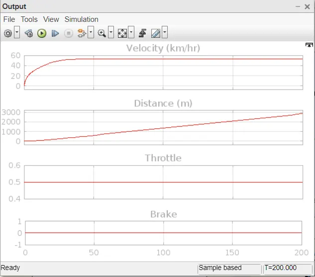
With Brake = 0, Step input at throttle,
CASE 2 - Open loop BAJA ATV Model with CVT using Dashboard
A Simulink model for the open loop BAJA ATV model with CVT using Dashboard is shown below:
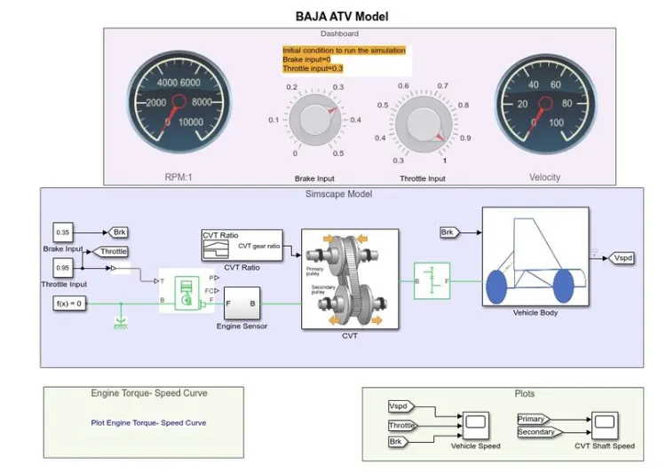
The working process is same as mentioned before , the only new block introduced here is that instead of using signal builder block we are using a Circular Guage block which acts like a speedometer wherein values can be displayed form the input knobs.
knob here is used to provide the input values of Brake and Throttle where we can set the knob placement as per the required value and conditions.
Else than this the entire process remains the same.
Resulted Graphs
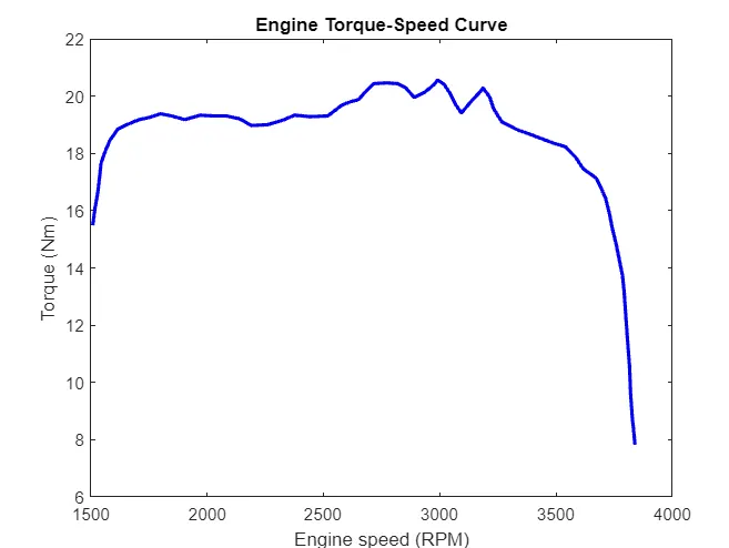
Tourque and speed curve from the default values of Brake=0 and Throttle=0.3
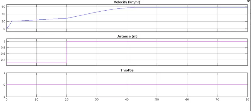
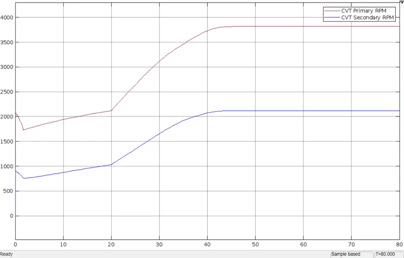
Observation:
a.) The torque at start is high as it is required for the initial pick up. With an increase in speed the torque is reduced and for the given input it is 8(N/m)
b.) The speed of vehicle increases gradually and becomes constant at certain level as seen in the velocity speed graph.
c.) The 0 value at the start used for driving gear which is represented by CVT primary RPM and then a sudden increase in the rpm is seen with less time.
CASE 3 - Closed loop BAJA ATV Model with CVT
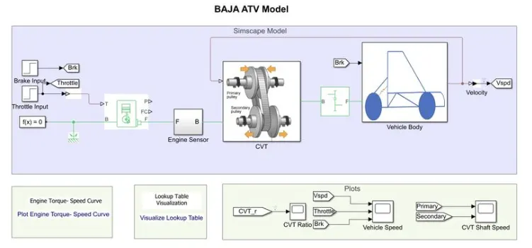
The figure below represents the Simulink model for the BAJA ATV using CTV for transmission using a closed loop by using Lookup Table:
New Blocks used in this model:
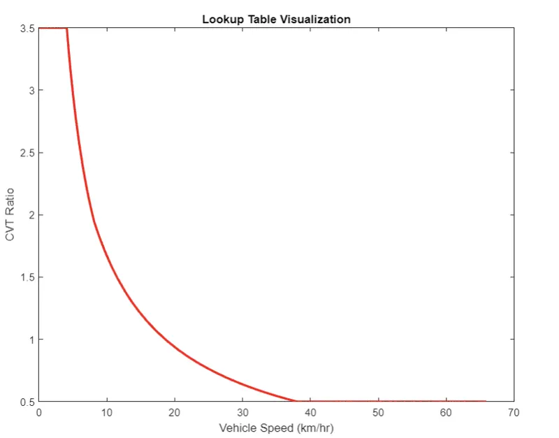
Lookup Table: It is defined as the array of data that maps input values to output and thereby resemles a mathematical function. With given input set of values , a lookup operation retreives the corresponding output values from table. In short it computes an approximation to some mathematical function. The lookup table in simulink generates an output based on the input values by using one of the methods selected from the Look-up method parameter list. If any input value isn't defined by lookup table , the block estimates the output values based on the nearby table.
In this model we are using the output signal from the vehicle body as the input to the CVT as the CVT gear ratio. This is loaded in workspace using a .mat file.
Step Block: The output is defined in the steps.
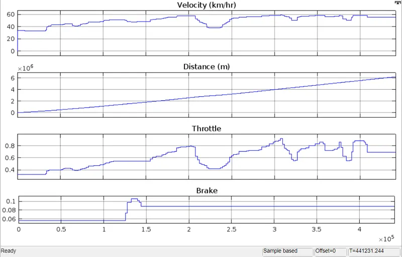
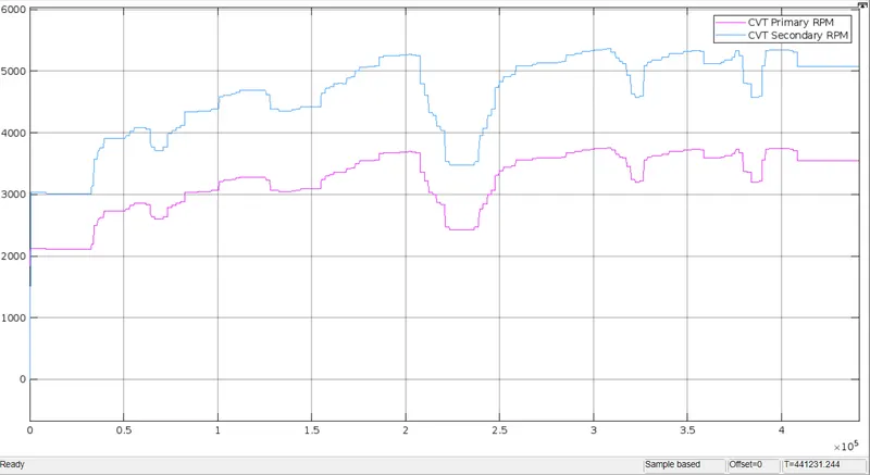
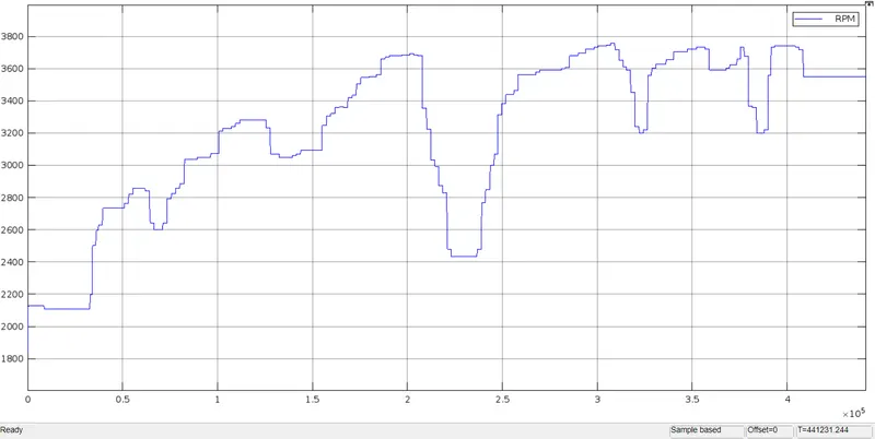
The working procedure is same is previous model with an addition of Lookup table block.
CASE 4 - Closed loop BAJA ATV Model with CVT using Dashboard
The model represented below shows the Simulink model for the BAJA ATV using CTV for power transmission using a dash board along with lookup table.
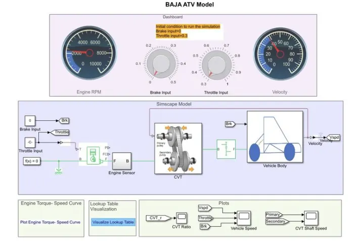
The process also remains the same as case 3 only change is that instead of step input, we are using a Circular gauge block which acts as a speedometer where values can be changed from the input knob.
Knob here is used to provide the input values for Brake and Throttle where we can set the knob as per required values and conditions.
The following process is similar as discussed before.
Resulted Graphs
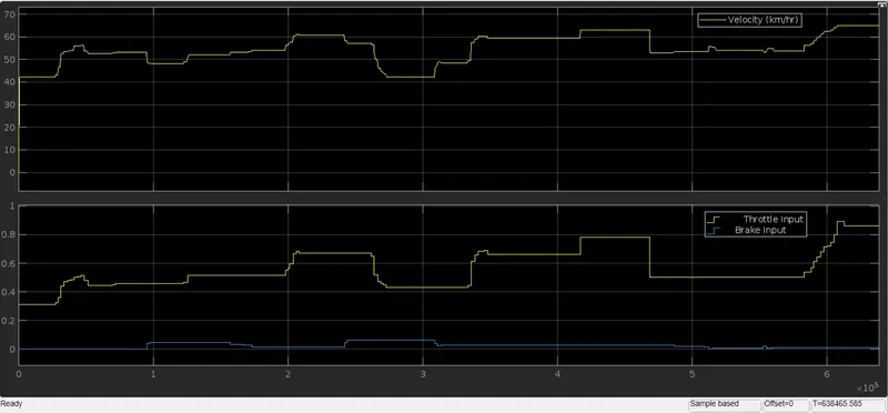
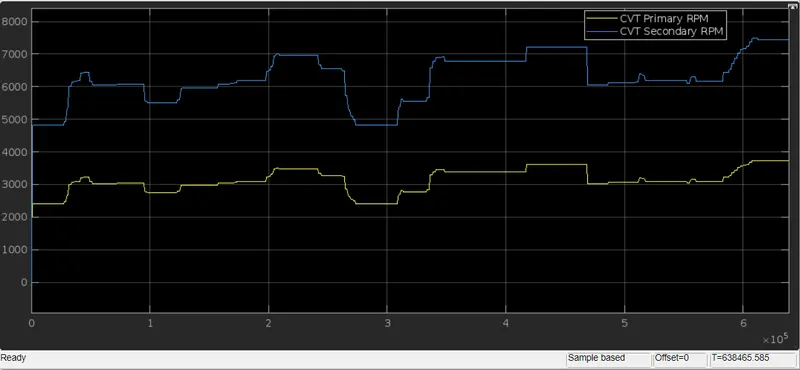
The output graphs of Vehicle speed vs time and CVT shaft speed are shown below:
Observation:
a) By using the lookup table, the vehicle speed increases gradually and takes longer to become constant at certain levelas we can see in the vehicle speed graph when compared to model without lookup table i.e., Open loop model.
b) The is a gradual increase in the speed at the secondary gear of the CVT as the initial speed is picked by the driving gear i.e., the primary CVT.
c) The look up table graph shows the CVT ratio with respect to the output power at the wheel.