Week - 4
Objective: To implement the control logic of a “washing machine” using Stateflow as per the given sequence:
- If the power supply is available, the system gets activated
- If the Water supply is not available, stop the process & indicate through LED
- Soaking time should be 200s followed by Washing time of 100s.
- Then rinsing happens for the next 20s & dryer runs for 50s
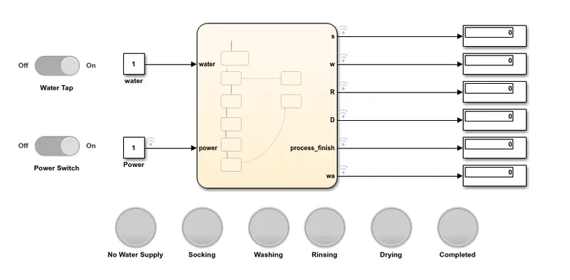
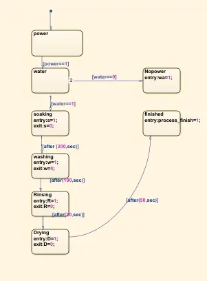
The Stateflow block and model of the washing machine logic are as follows.
Blocks used:
1. Constant: used to feed input values to the state flow.
2. Slider switch: used to vary the input of the state flow.
3. Display: Used to check the output of the Stateflow.
4. Lamp: Used to indicate the output of the Stateflow.
5.Stateflow: Defined states with required variables like power, water, soaking, washing, rinsing, drying, and process complete.
Explanation:
- the power and water supply to the Stateflow of the washing machine are varied on/off position with the slider switch.
- Stateflow is built to follow the given instructions.
- When there is no power Stateflow of the machine is not active. The machine will get activated only when the power is on.All indications are off.
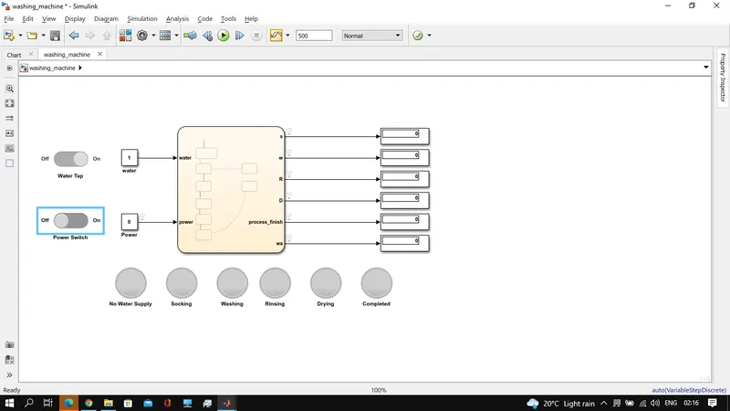
- when power is on and the water tap is not on.The machine will indicate the no water supply with Red color lamp indication.
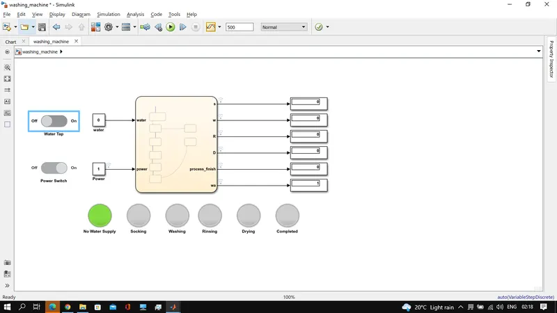
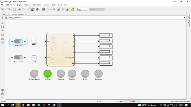
- When both the power and water supply are available. The Stateflow starts proceeding to the next stage in the flow. i.e soaking.
At simulation time of 20sec- the result is attached.
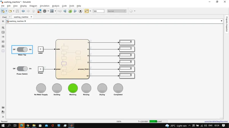
- After the Stateflow finishes, the machine will start washing for 100secs. the result at a simulation time of 210 secs is attached.
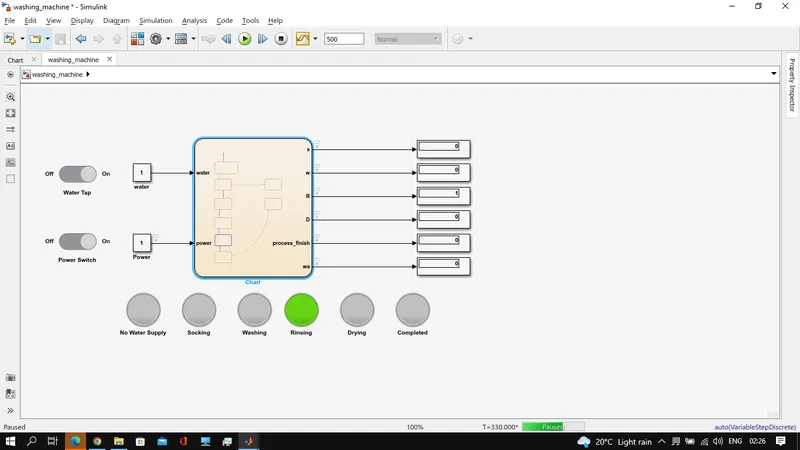
- Later, machine rinses 20secs, result at 330sec is attached.
- finally, drying will happen for 50secs. the result has been shown below.
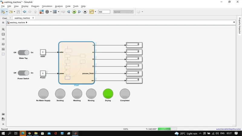
- After drying the machine will indicate the process is complete.
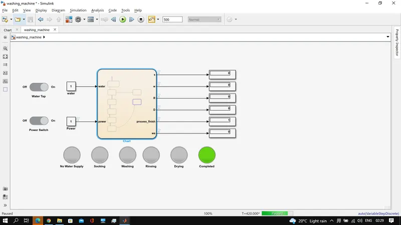
----------------------------------------------------------------------------------------------------------------------------------
Objective: To Make a Stateflow for the “Gear shift” logic as per given conditions to display the gear number for the input speed,
Speed Range(kmph) Gear
0 to 15 1
16 to 25 2
26 to 40 3
41 to 60 4
Above 61 5
Blocks used:
1. Constant: used to feed the speed value to the Stateflow
2.Slider: used to change the speed during simulation time.
3. Speed gauge: used to represent the speed visually in a guage
4. Scope & display: used to check the results.
5. Stateflow: Defined states, variables, and conditions.
Model& Stateflow:
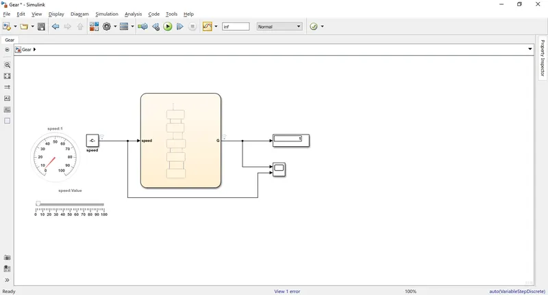
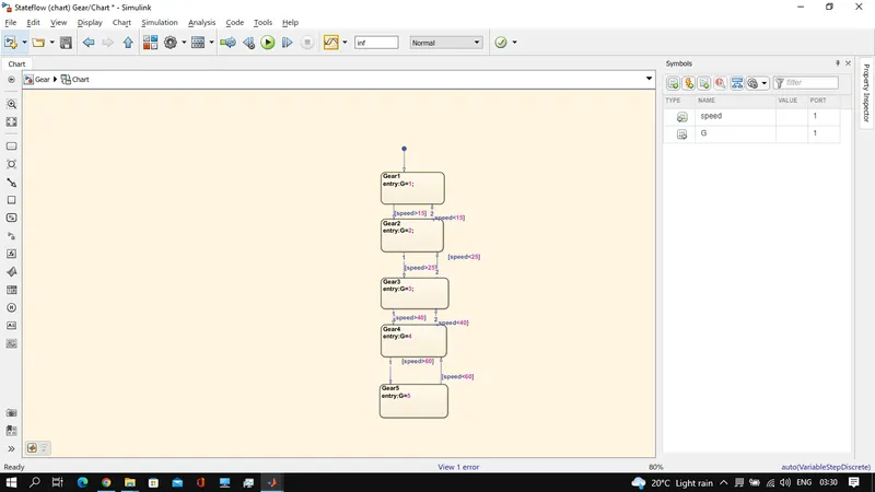
Explanation:
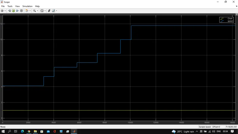
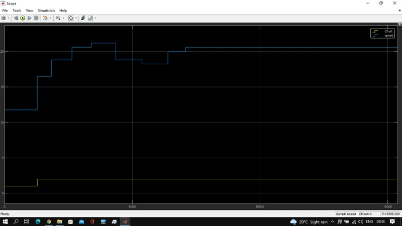
- If speed input is <15 then the gear remains in first gear. Later, if speed>15 then the gear shifts to 2nd gear.
 .
.
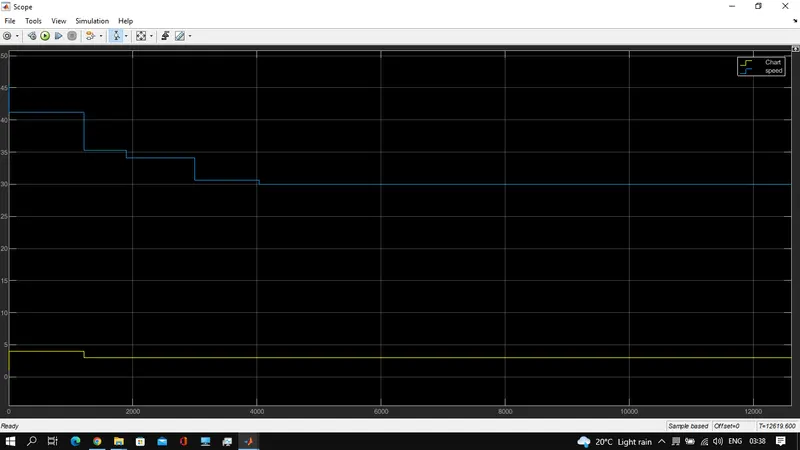
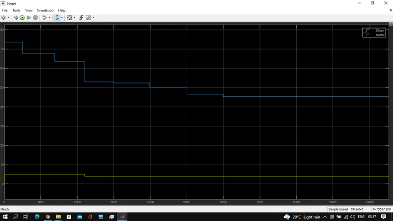
- if speed>25 shifted to 3rd gear,>40 4th gear, >60 5th gear.
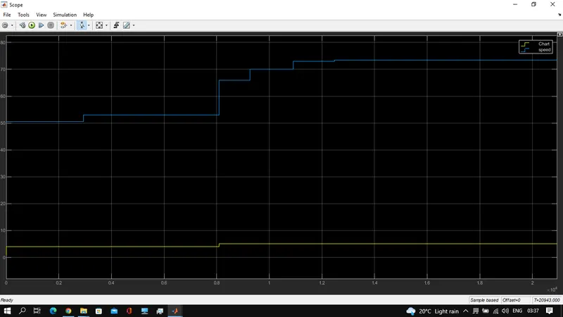
- Stateflow works perfectly for the given conditions
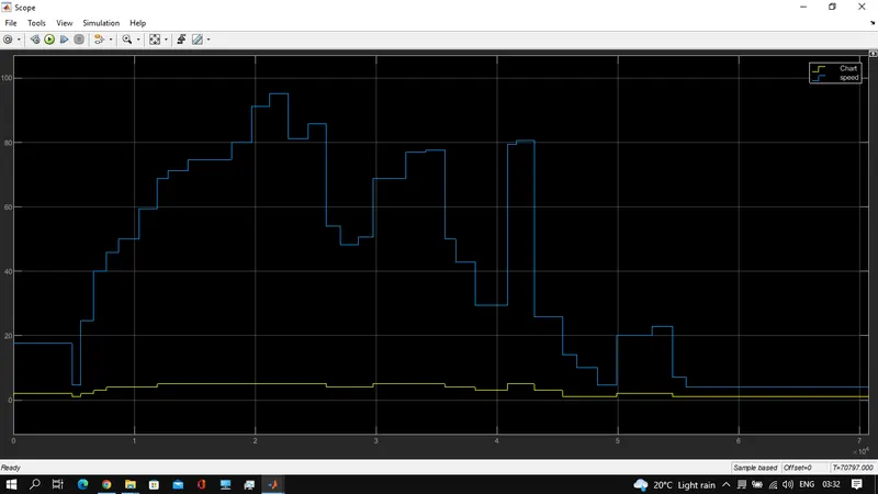
Results: The slider changed during the simulation and the results are attached below. stateflow gear system is working well as per the given conditions.