Week -2
Aim:
To prepare a Simulink model of a doorbell using a solenoid block with the following details
- When the switch is closed, the solenoid should receive power from the battery.
- Once after receiving power, how solenoid is generating the physical force to hit the bell.
- As per the question, the switch is configured to close for 2 seconds.
Components/Blocks needed: the following blocks are used to create the model as required.
- Solenoid block: an electromagnetic device that is represented as a doorbell. This block takes the electrical energy and exhibits the mechanical parameters like the force and stroke of a plunger.
- DC Battery source: This is needed to act as a source in the electrical circuit.
- Ideal Translated Motion Sensor: To generate output for the position input of the plunger.
- Pulse Generator: To create the analog input change to the switch
- PS-Simulink: To converter from Physical systems to Simulink signals
- Simulink-PS: To converter from Simulink signals to Simulink signals
- Electrical and Mechanical references: to provide reference electrical and mechanical signals.
- Switch: this block is used to connect and disconnect the electrical circuit.
- Solver & scope: general requirements to solve and view the results respectively.
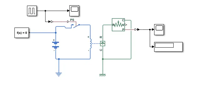
The model snap shot is shown above.
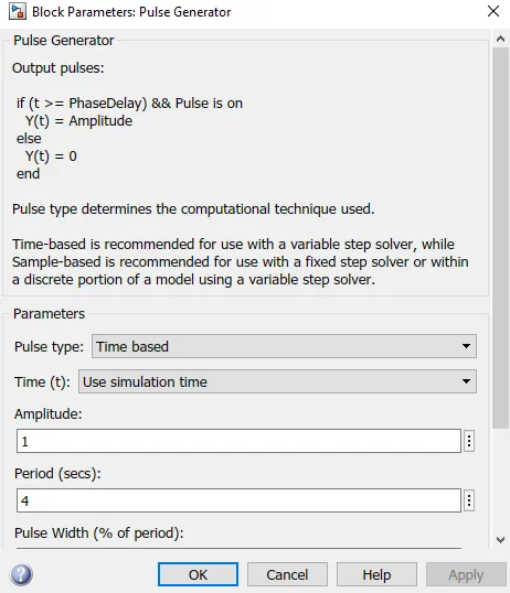
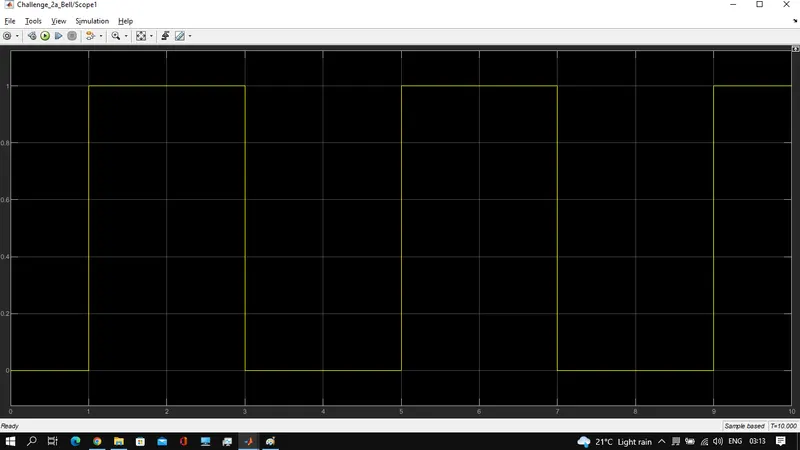
- The switch is closed for 2secs, out of 10sec simulation timings as shown below. 3 times switch has been closed.
(Pulse mag is 1 and switch threshold is 0.5)
- Output of the solenoidal physical signal is attached below.
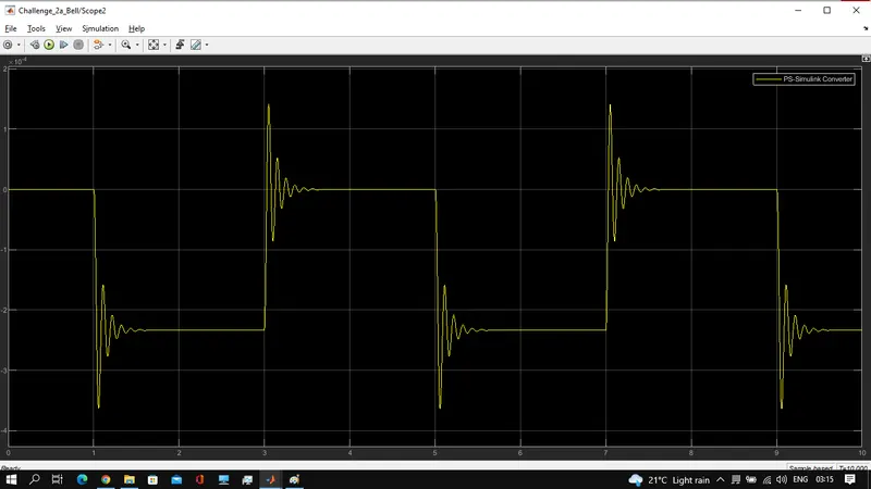
Conclusion: required model is prepared and simulated. the solenoid switch is closed for 2secs and the physical plunge moment results are shown.
----------------------
Aim: Use a thermistor to sense the temperature of a heater and turn on or off the fan as per the below conditions.
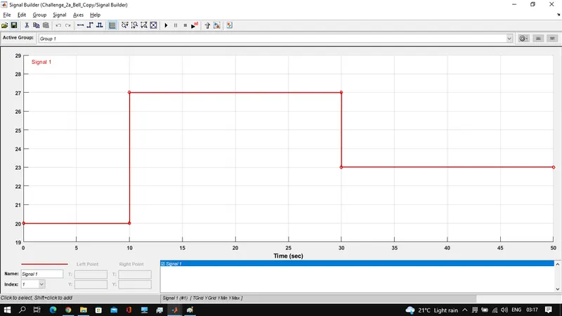
Temperature source : 20Deg.C from 0 to 10sec; 27Deg.C from 10 to 30secs,23Deg.C from 30 to 50 seconds.
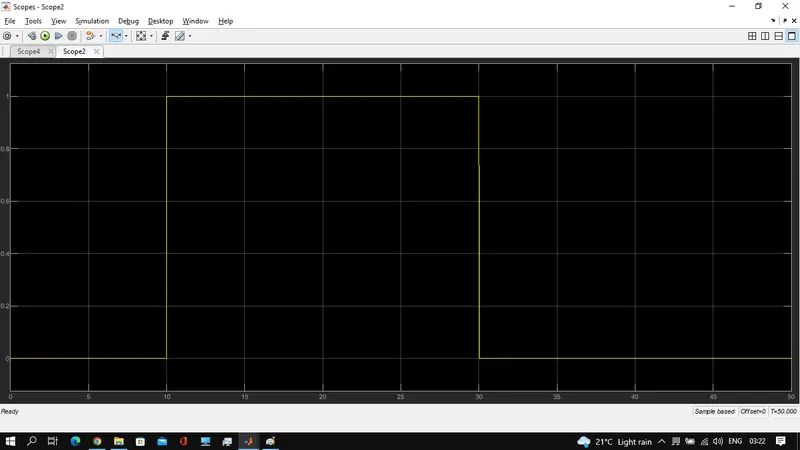
Fan condition: on if the temperature is above 25deg.c off otherwise
To prepare a model using a thermistor, if the heater temperature is more than 25 deg.C fan switch on command shall be generated for the given temperature conditions as mentioned above and plotted in the following figure.
Components needed: the following blocks are used to create the model as required.
- PTC Thermistor: used to increase the resistance beyond the set temperature value. This block takes temperature input from the thermistor.
- Controlled temperature source: this block is used to act as a temperature source. It takes the physical temperature parameter as input compares with port-A and provides the gradient at port-B.
- Signal builder: this block is used to create the Simulink temperature at a different time to feed to the controlled temperature source.
- PS-Simulink: To converter from Physical systems to Simulink signals
- Simulink-PS: To converter from Simulink signals to Simulink signals
- Electrical and Mechanical references: to provide reference electrical and mechanical signals.
- DC Battery source: This is needed to act as a source in the electrical circuit.
- Solver & scope: general requirements to solve and view the results respectively.
- Voltage sensor: measures the voltage between the nodes connected.
- Switch: used to close and disconnect the circuit. Here, based on the voltage drop across the resistor. The threshold in the switch is defined to get the fan switch closed command.
The model for the required arrangement is as shown below.
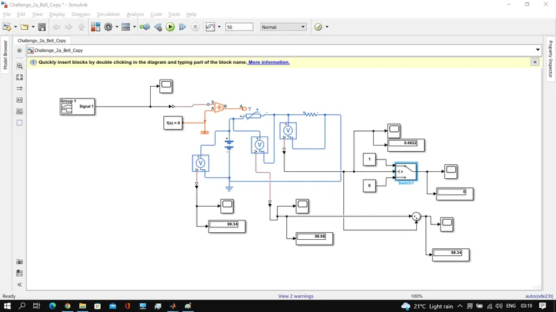
As shown at the start, the signal builder block is used to generate the temperature at different simulation timings.
- Later, the simulation temperature parameter is converted to the physical parameter and fed to a controlled temperature source.
- The physical temperature gradient is fed to the PTC thermistor to calculate the resistance for the corresponding increase in temperature.
- Accordingly, the drop across the PTC thermistor will increase during the high-temperature time.
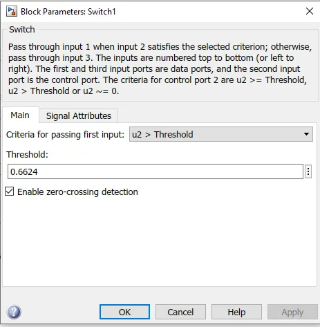
- Accordingly, the threshold is given in the switch to give on command to the fan.
Hence the on command is given to the fan switch,from 10sec to 30sec, where the temp is beyond 25Deg.C. Hence, teh required simulation is done.
The switch threshold is calculated, at 25deg.C what is the drop across the resistor is calculated above which the switch closed command is generated.
.
Conclusion: the model is prepared and executed successfully; from 10sec to 30sec the temp is above 25deg.C, accordingly, during that particular time the fan will be switched on for the given input temperature conditions.
.