Week - 4
1. Implement control logic of a “washing machine” using Stateflow as per given sequence:
- If the power supply is available, the system gets activated
- If the Water supply is not available, stop the process & indicate through LED
- Soaking time should be 200s followed by Washing time of 100s.
- Then rinsing happens for next 20s & dryer runs for 50s
After all the processes have completed turn on the finished LED.
Program :-
Script of Stateflow :-
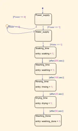
Script Discription :-
- In this chart there is two inputs are define which are power supply and water supply.
- In that process loop is only activate if power supply start. Which give 1 value to stateflow chart which means power supply is on. Otherwise 0 value written by system and program is not started.
- This procedure is same for water supply.
- After getting 1 value for both input like power and water, process cycle is start.
- First of all soaking process is starting. It gives 1 output value to indication of process start.
- Then soaking block connected with washing block by condition of after(200,sec). Which means after soaking process start, till 200sec soaking process is running. After that washing process is starting. As washing process start it also give 1 value as output.
- This washing block connected to rinsing block by 100 second cycle time condition. Which means washing is over and rinsing start after 100sec. As rinsing process start it also give 1 value as output.
- Drying block is followed by rinsing block with 20 second condition. Which means rinsing is over in 20 sec after that drying process start. As same as others it gives 1 output value when process get active.
- Drying process is running for 50 second as given in condition. It also give 1 value a output.
- After all cycle get completed last block is connected to indicate washing process status which is done. So, we can see that all process is done and washing process is completed.
- As usual it also set to give 1 value as output when block activated.
- For all above block if block is not activated it shows 0 value by default.
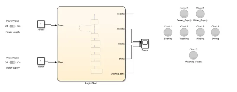
Program Description :-
- After creating script like above, two constant block is connected to two inputs which are power supply and water supply by sliding switch.
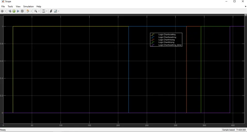
- Output values from stateflow block is connected to scope to see activation time.
- Also, lamp is connected with the value of outputs to indication of process status.
Output :-
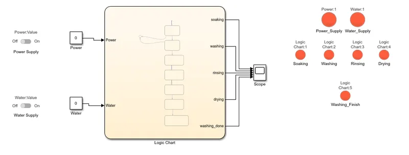
1. Power and Water supply OFF
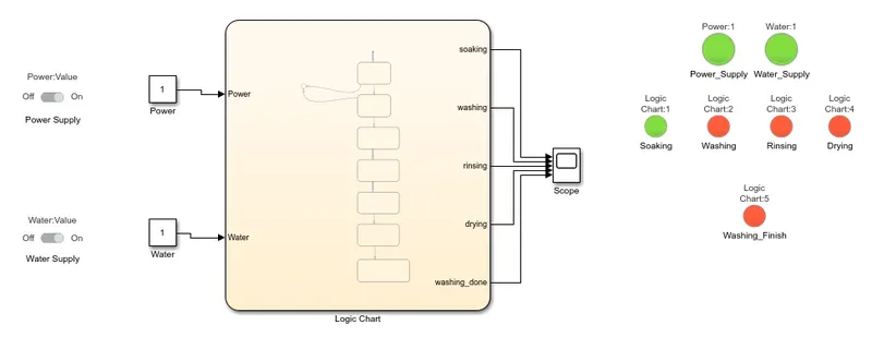
2. Power and Water supply on and run for 200sec
3. Running for 300sec
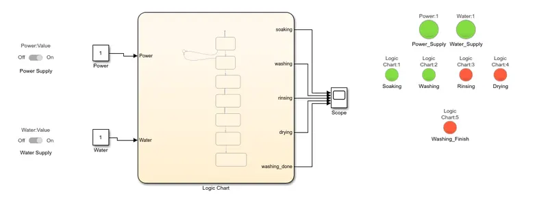
4. Running for 320 sec
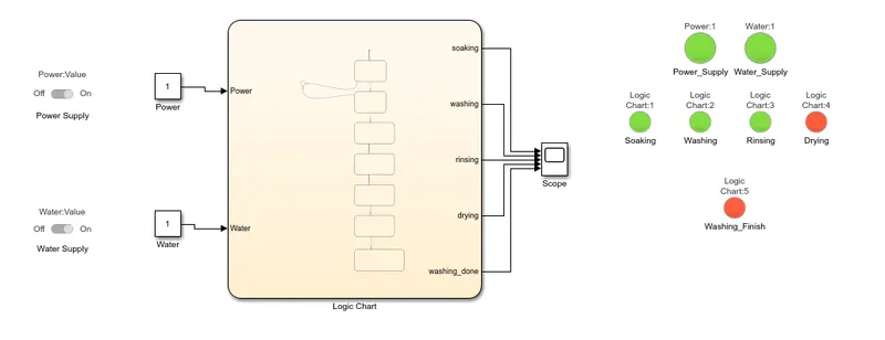
5. Running for 370sec
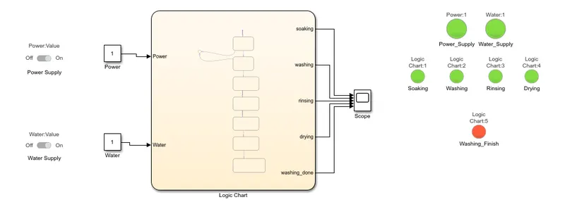
6. Running for 420sec
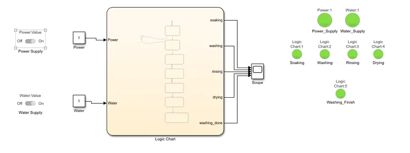
Scope :-
Conclusion :-
- As shown is scope every process iss get activated as predefined cycle time and finish washing cycle automatically in defined time.
2. Make a Simulink chart for the “Gear shift” logic as per below conditions:
Speed Range(kmph) Gear
0 to 15 1
16 to 25 2
26 to 40 3
41 to 60 4
Above 61 5
Give speed input while the simulation is running & display the gear number.
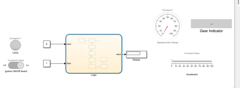
Program :-
Script :-
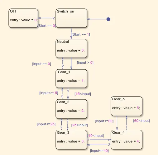
Script Discription :-
- As in car or bike we need to switch on to start bike.
- So, like that here slider switch is connected to switch on/off block in stateflow chart. If switch is on then it shows 1 value as output otherwise shows 0 value.
- Stateflow chart is activated and show gear shifting only if switch is on and output value is 1.
- Now second input is speed. Which variable name is define as input in stateflow chart.
- While input value is zero during staring which indicates neural gear. Which give 0 value as output.
- This block is connected to gear 1 indication with 1 output value by input>0 condition. Which means spped is increase from 0 vehicle run in gear 1.
- Thi gear 1 block is connected with gear 2 block with 2 output value. This block are shifting when input value is being geater than 15.
- When speed is increase than 25 gear 3 is shifted which is connected with this condition to gear 2 block. It shows 3 as output value.
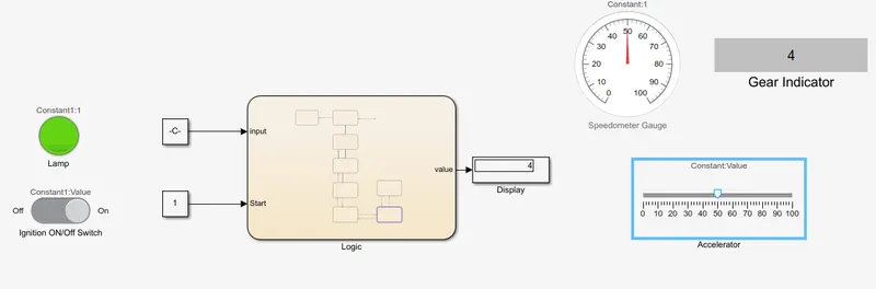
- Above 40 speed gear 4 is shifted and it indicate 4 value as output.
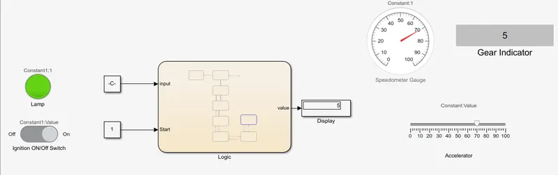
- Then last gear 5 is connected to gear 4 block with condition of speed greater than 60. It gives output value 5.
- So, this is one sided speed increment stateflow.
- But we also need to connect block with reversal stateflow because in actual speed is not always increase.It decreases also.
- So, gear 5 to 4 block is connected with speed value less than or equal to 60.
- Like that gear 4 to 3, 3 to 2, 2 to 1, 1 to 0 is connected with speed value 40, 25,15 and 0 respectively.
- Like this stateflow script is defined.
Program Description :-
- This stateflow script has two input value which are ingnition start and vehicle speed.
- Ignition start input is connected with constant block with sliding switch to give ON/OFF command.
- Also lamp is connected to see igniion switch ON/OFF status.
- Speed input value is connected with constant block by slider block to give input values during simulation.
- This input value is connected to speedometer block to see speed of vehicle.
- Stateflow output is only one which indicates gear position with respect to speed.
- This output value is connected to the scope. And also connected to the display block to see gear number at given input speed.
Output :-
1. Ignition off
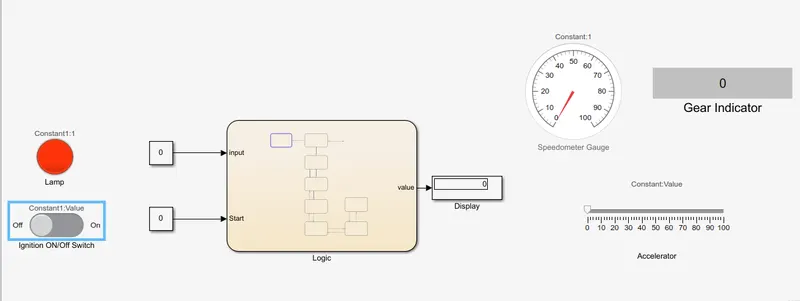
2. Ignition ON and Speed 0
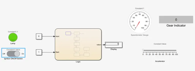
3. At speed of 10
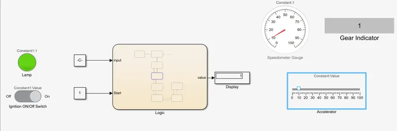
4. At speed of 20
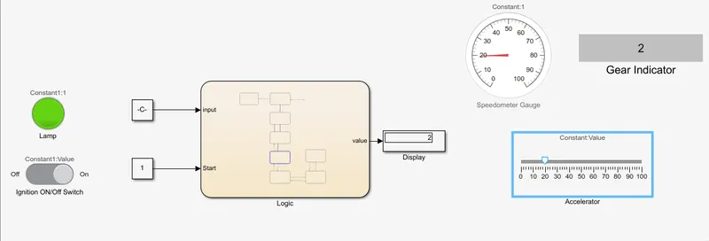
5. At speed of 30
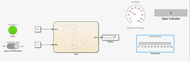
6. At speed of 50
7. At speed of 70
Conclusion :-
- So like this script is generated and it computed gear indication value from stateflow chart defined condition values.