Week - 4
Aim:
To implement the Control logic of the washing machine and gearshift mechanism using stateflow.
OBJECTIVE:
1. To implement the control logic of the washing machine using state flow as per given sequence:
- if the power supply is available, the system gets activated.
- If the water supply is not available, stop the process and indicate through LED.
- 4. Soaking time should be 200 seconds followed by washing time off hundred seconds.
- 5. Then rinsing happens for the next 20 seconds and dryer runs for 50 seconds.
- 6. After all the process have completed turn on their finish LED.
PROCEDURE AND STEPS:
- 1. Create a chat block for defining the stateflow.
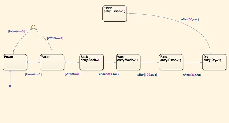
- Inside it, the circular junction is to terminate the signal flow and return a null valve.
- If power is OFF I.e. 0, the process is terminated at the junction else 1 is carry forwarded.
- Use water is OFF i.e.0, the process he's terminated at the junction else 1 carry forwarded.
- After this, soak block get activated and soaking action takes place.
- After 200 sec of soaking, wash block gets activated and washing action takes place.
- After 100 sec of washing, rinse block get activated and rinsing action takes place.
- After 20 sec of rinsing, dry block gets activated and drying action takes place.
- After 50 sec of dry, finish block get activated. Finish is to terminate the signal flow in the process and exits the chat.
- Define power and water as inputs where as soak, wash, Rinse, dry, finish as outputs.
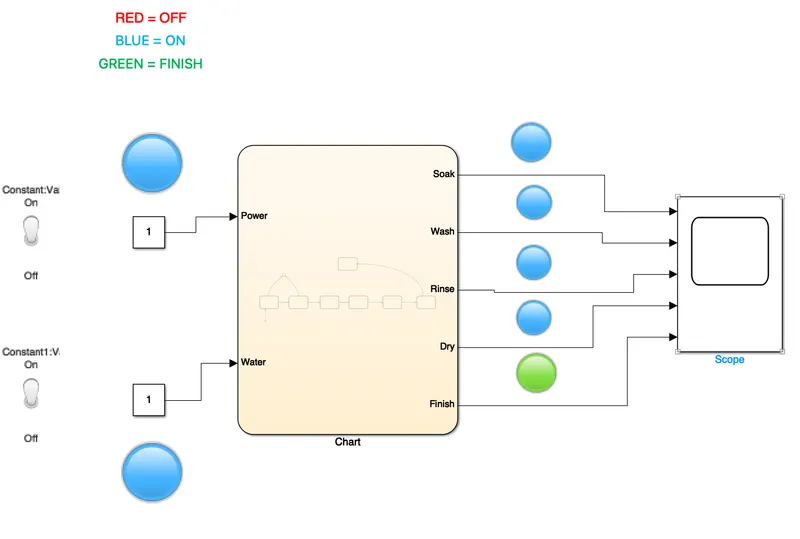
- Connect the chart block with the constant blocks for power and water inputs. Inputs switches connected to them are toggle switchs respectively (to distinguish between the two). Attach lamps to observe the ON/OFF condition.ON is blue, OFF is red
- A common scope block is connected to observe the entire washing process and obtain the output plot. Green color in the lamp that indicates the process is completed.
Simulink model for operating the according to the given conditions is shown below.
SIMULINK MODEL:
STATEFLOW MODEL:
Input for POWER,ON WATER,OFF
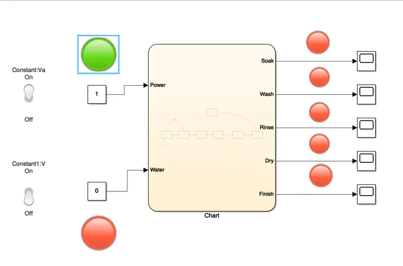
Output for 0 sec is given below
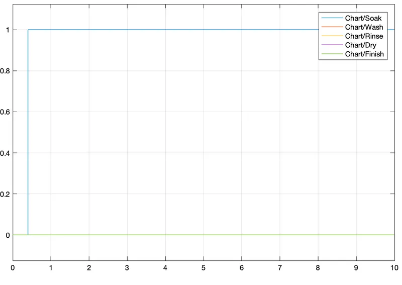
POWER ON, WATER ON, SOAK ON for 10 sec.
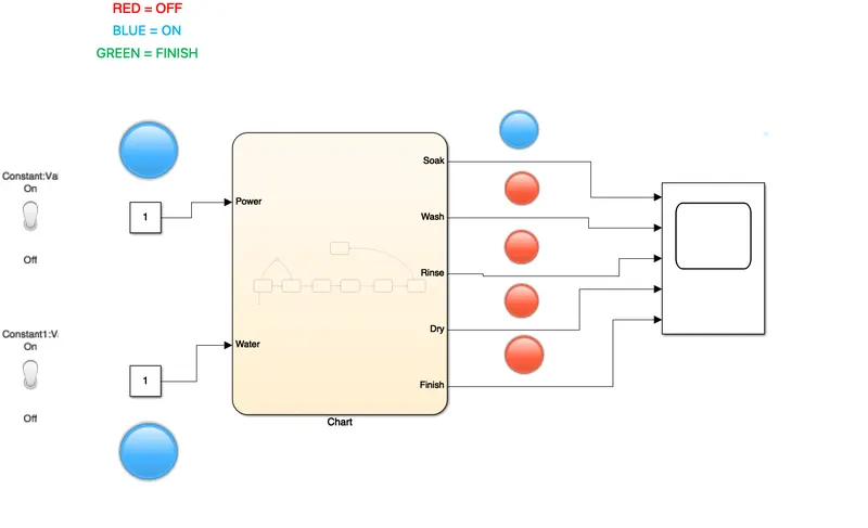
output for 10 sec.
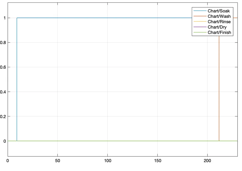
POWER ON,WATER ON, WASH ON, For 230 sec.
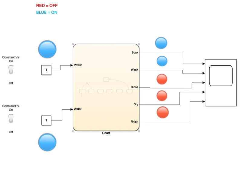
Output for 230 sec.
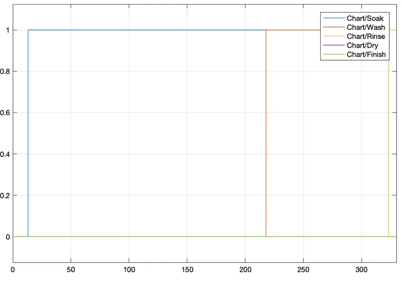
POWER ON, WATER ON, RINSE ON for 330 sec
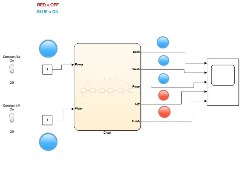
output for 330 sec.
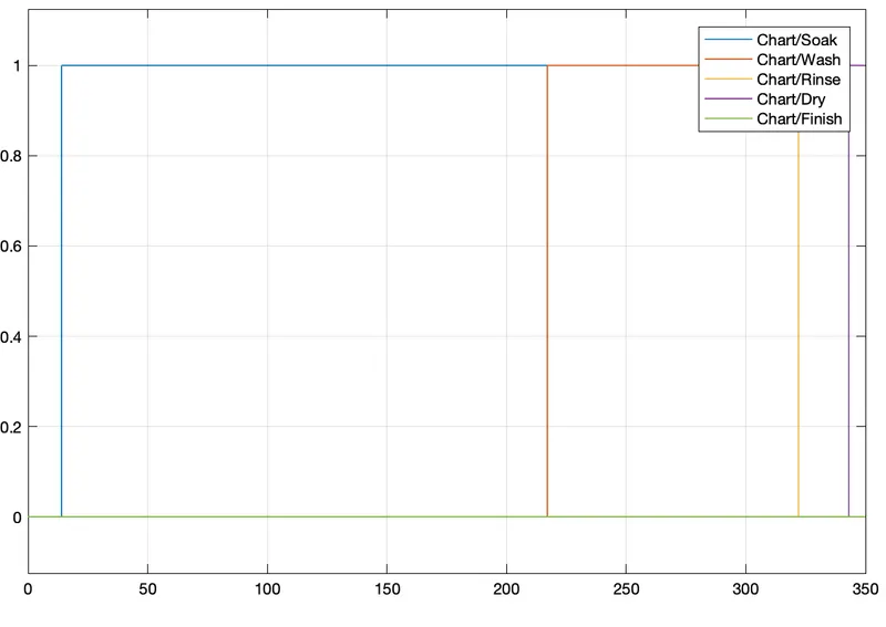
POWER ON, WATER ON, DRY ON, for 350 sec.
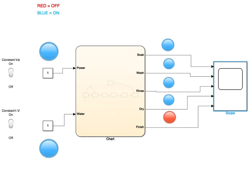
Output for 350 sec.
POWER ON, WATER ON. FINISH ON, for 500 sec.
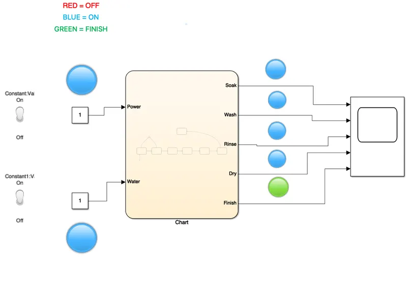
output for 500 sec.
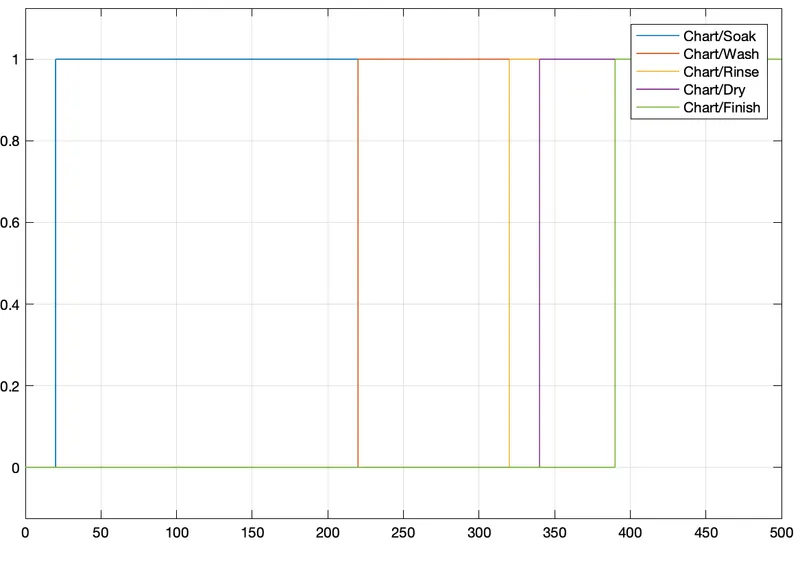
OBJECTIVE 2:
To make a simulink chart for the gear shift logic as per below conditions.
GEAR: 1 2 3 4 5
SPEED: 0-15 16-25 26-40 46-60 61 above
Give the speed input while the simulation is running and display the gear number.
WORKING:
In a gear box, the teritiary counter shaft is mashed to the clutch with the use of a couple gears. So the counter shaft is always in running condition. When the teritory shat is brought in contact with the main shaft by the use meshing gears, the main starts to rotate according to gear ratio when the driver want to change the gear ratio simply press the clutch pedal with disconnects the territory shaft with the engine and connect the main shaftwith the territory shaft by another gear ratio by the use of gear shift lever.
PROCEDING STEPS:
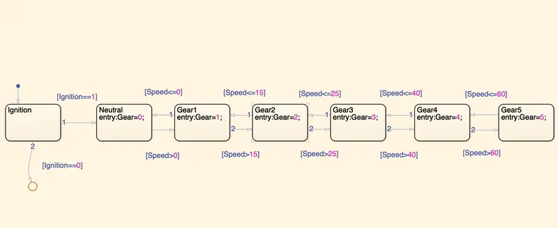
- Create a chart block for defining the stateflow as per the given conditions.
- Inside it. The circular junction is to terminate the signal flowand return a null valve.
- If the ignition is OFF i.e 0, the process is terminated at the junction else 1 is carry forwarded.
- If speed is less than or equal to 0 the flow is terminated and the gear 0 is activated at the junction else 1 is carry Forwarded.
- if the speed is greater than 0 and less than or equal to 15 the flow is terminated and the gear one is activated.
- if the speed is greater than 15 and less than or equal to 25, the flow is terminated and gear 2 is activated.
- if the speed is greater than 25 and less than or equal to 40, the flow is terminated and the gear 3 is activated.
- If speed is greater than 40 and less than or equal to 60, the flow is terminated and the gear 4 is activated.
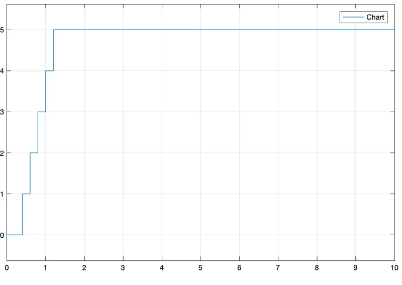
- if the speed is greater than 60, the flow is terminated and the gear 5 is activated.
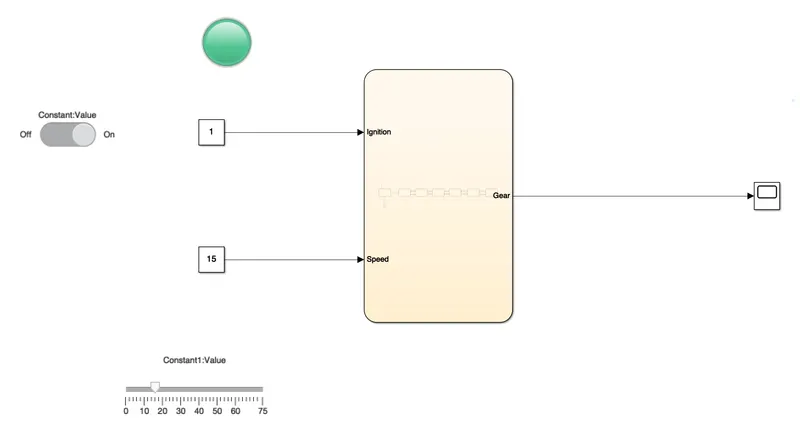
- define ignition and speed as inputs the output is displayed on the scope.
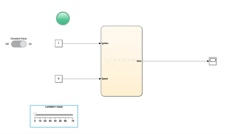
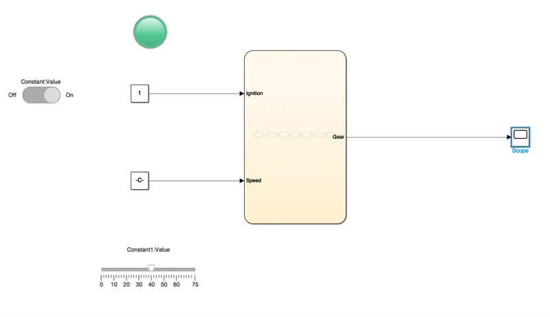
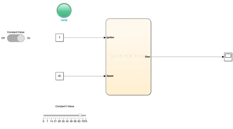
- conmect the chart block with constant blocks foe ignition and speed inputs the slider swith and slider bar is connected as a inputs to adjust variable speeds respectively a lamp is attached to observe the on off condition.
- A common scope block is connected to observe the speed numericaly to obtain the ouput plots.
A simulink model for operating a gearshift mechanism according to given conditions is shown below.
SIMULINK MODEL:
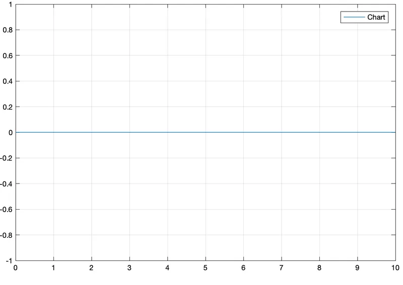
STATEFLOW CHART:
IGNITION ON, SPEED 0-15, GEAR 1.
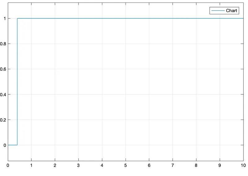
IGNITION ON, SPEED 16-25, GEAR 2.
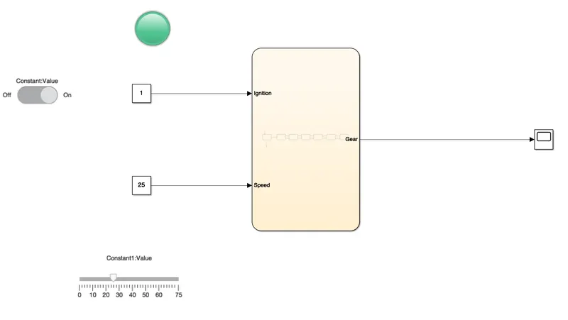
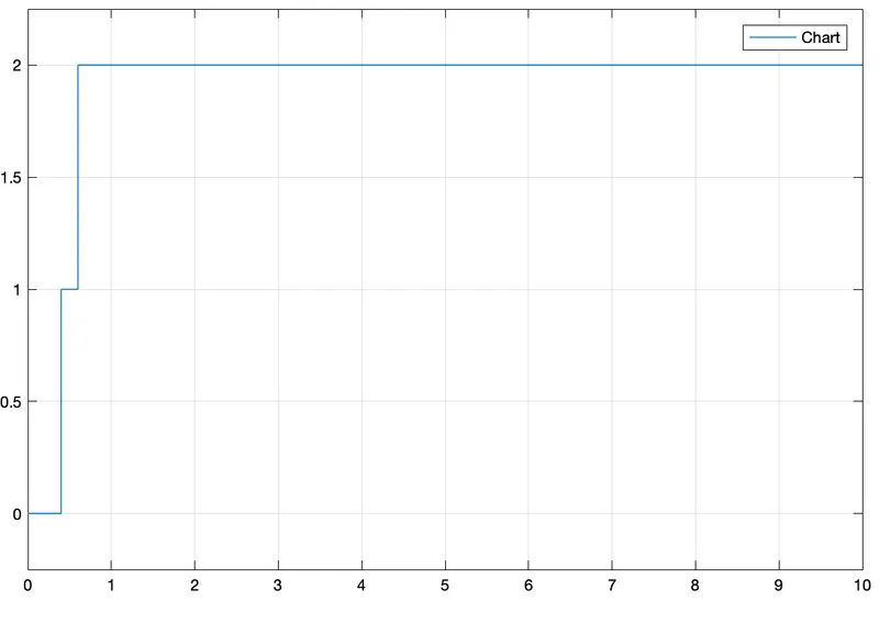
IGNITION ON, SPEED 26-40, GEAR 3
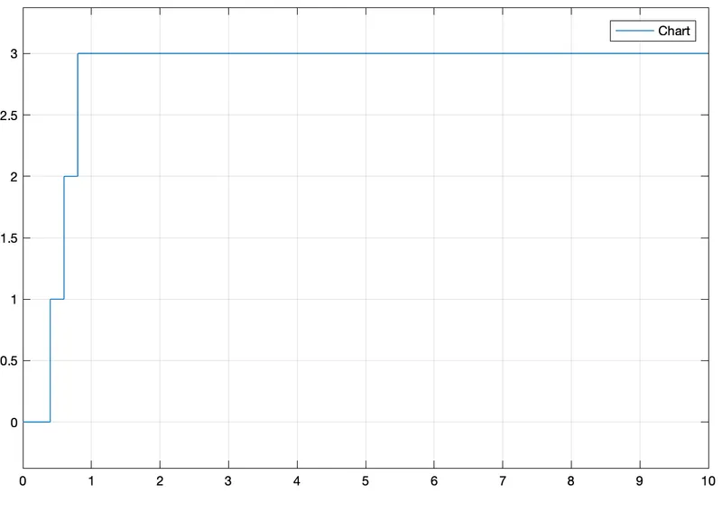
IGNITION ON, SPEED 46-60, GEAR 4.
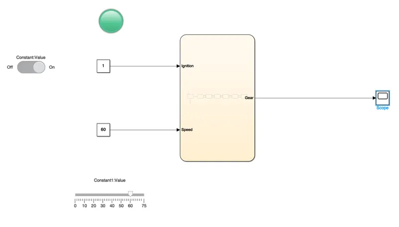
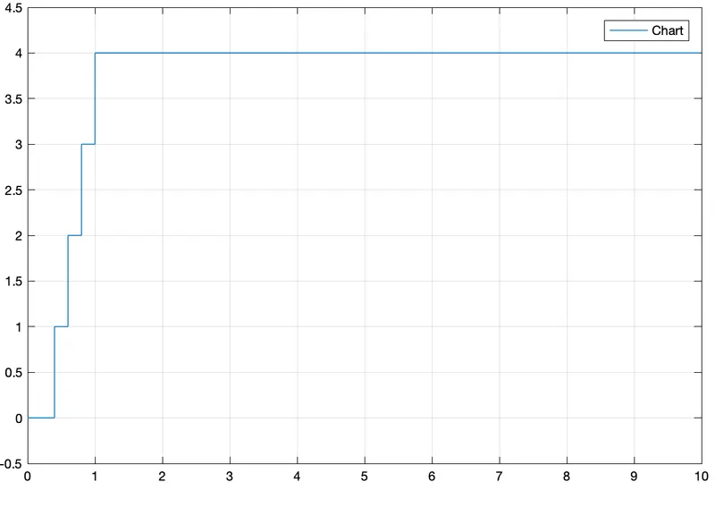
IGNITION ON, SPEED ABOVE 60, GEAR 5.
CONCLUSION:
Hence the given problem was simulated for the washing machine and gearshift mechanismand executing the stateflow as per according to given conditions.