Week - 4
Aim
- To implement control logic of a “washing machine” using Stateflow as per given sequence.
- Make a Simulink chart for the “Gear shift” logic.
Objective
Using control logic of a “washing machine” using Stateflow as per given sequence:
- If the power supply is available, the system gets activated
- If the Water supply is not available, stop the process & indicate through LED
- Soaking time should be 200s followed by Washing time of 100s.
- Then rinsing happens for the next 20s & dryer runs for 50s
After all the processes have been completed turn on the finished LED
Introduction
- State Flow
- State Flow is a technique to convert a flow-chart or logic into a systematical arrangement.
- It provides a graphical language that includes state transition diagrams, flow charts, state transition tables, and truth tables. You can use State flow to describe how MATLAB algorithms and Simulink models react to input signals, events, and time-based conditions.
- State flow enables you to design and develop supervisory control, task scheduling, fault management, communication protocols, user interfaces, and hybrid systems.
- State Machine
- Model of systems whose behavior can be modeled as a set of states and transitions between states. These systems are sometimes called reactive systems.
- A finite state machine is a representation of an event-driven (reactive) system. In an event-driven system, the system responds to an event by making a transition from one state (mode) to another. This transition occurs if the condition defining the change is true.
- A State flow chart is a graphical representation of a finite state machine. States and transitions form the basic elements of the system.
- State
- Stages include used in a system, or operating modes of the system.
- Control Logic
- Control Logic is a key part of a software program that controls the operations of the program.
- The control logic responds to commands from the user, and it also acts on its own to perform automated tasks that have been structured into the program.
- Control logic can be modeled using a state diagram, which is a form of the hierarchical state machine.
Theory
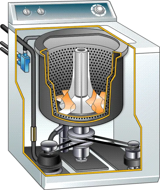
- A washing machine is a home appliance used to wash laundry. The term is mostly applied to machines that use water as opposed to dry cleaning or ultrasonic cleaners. The user adds laundry detergent, which can be either liquid or in powder form.
- A washing machine by spinning at 800 – 1600 rpm helps soap and dirt with it to leave the surface of the cloth via centrifugal force and into outlet pipes hence utilizing centrifugation to both clean and partially dry the clothes loaded in it.
- The processes are electrically controlled, such as the drum, valves, pump, motor, and heating.
- The valve opens again and the dirty water drains out of the drums.
- The pump works to help get rid of the water.
- The valve lets clean water in again into the drums.
Procedure
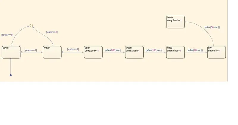
- Create a chart block for defining the Stateflow as per the given conditions.
- Inside it, the circular junction is to terminate the signal flow and return a null value.
- If power is OFF i.e., 0, the process is terminated at the junction else 1 is carried forward.
- If water is OFF i.e., 0, the process is terminated at the junction else 1 is carried forward.
- After this, the Soak block gets activated and soaking action takes place.
- After 200 sec of soaking, the wash block gets activated and washing action takes place.
- After 100 sec of washing, the Rinse block gets activated, and the rinsing action takes place.
- After 20 sec of rinsing, the Dry block gets activated and drying action takes place.
- After 50 sec of drying, the Finish block gets activated. The finish is to terminate the signal flow in the process and exists the chart.
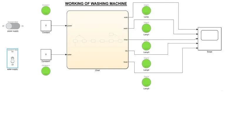
- Define power and water as inputs whereas soak, wash, rinse, dry, and finish as outputs.
- Connect the chart block with constant blocks for power and water inputs. Input switches connected to them are a slider switch and a toggle switch respectively (in order to distinguish between the two). Attach lamps to observe the ON/OFF condition.
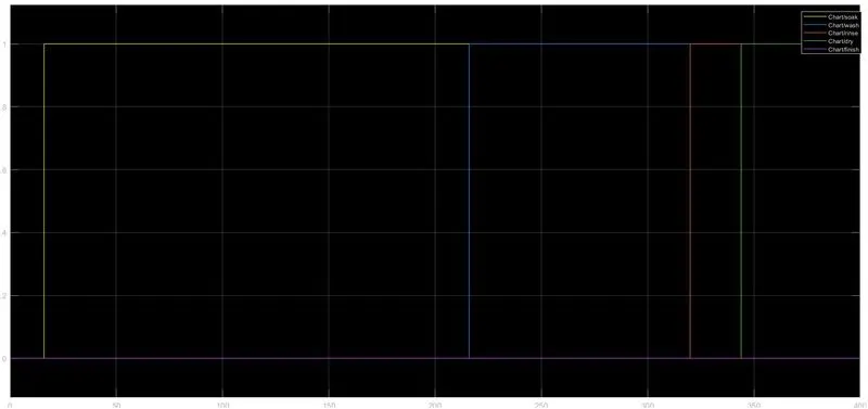
- A common scope block is connected to observe the entire washing process and obtain the output plot. The blue color in the lamp indicates that the process is complete.
Simulink Model
State flow
Conclusion
- To understand the basics of State flow, State machines, and Stages of the system.
- We learn how logic is made and applied the condition to fulfill the requirement.
- We learn the logic used in processing the washing machine.
#Part: -2
Objective
- Make a Simulink chart for the “Gear shift” logic as per below conditions:
Speed Range(kmph) Gear
0 to 15 1
16 to 25 2
26 to 40 3
41 to 60 4
Above 61 5
Give speed input while the simulation is running & display the gear number.
Theory
The transmission box which is also known as the gearbox is the second element of the power train in an automobile. It is used to change the speed and torque of the vehicle according to a variety of road and load conditions. The transmission box changes the engine speed into torque when climbing hills. Sometimes it is known as a torque converter.
The main functions of the gearbox are as follows: -
- Provide the torque needed to move the vehicle under a variety of road conditions. It does this by changing the gear ratio between the engine crankshaft and vehicle drive wheels.
- Be shifted into reverse so the vehicle can move backward.
- Be shifted into neutral for starting the engine.
Working
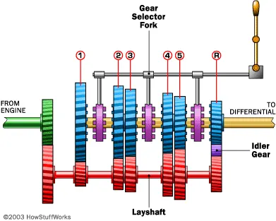
In a gearbox, the tertiary shaft is mashed to the clutch with the use of a couple of gears. So, the countershaft is always in running condition. When the tertiary shaft is brought in contact with the main shaft by the use of meshing gears, the main shaft starts to rotate according to the gear ratio. When the driver wants to change the gear ratio, simply press the clutch pedal which disconnects the tertiary shaft with the engine and connects the main shaft with the tertiary shaft by another gear ratio by use of the gearshift lever.
Procedure
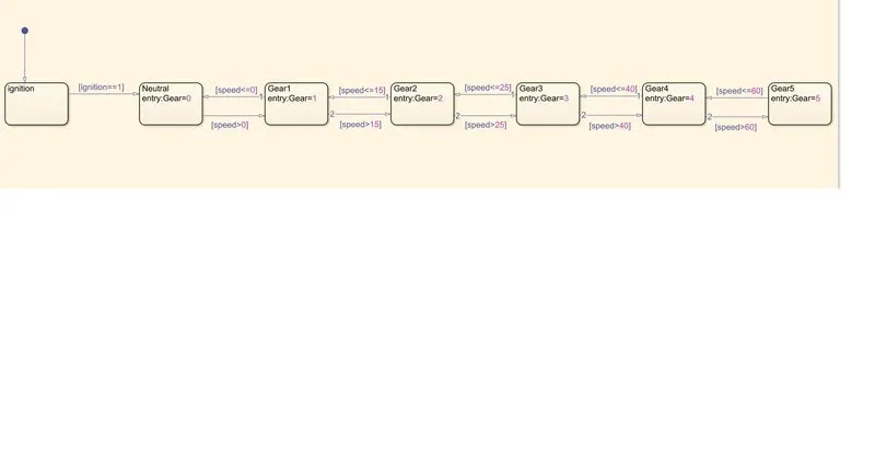
- Create a chart block for defining the state flow as per the given conditions.
- Inside it, the circular junction is to terminate the signal flow and return a null value.
- If the ignition is OFF i.e., 0, the process is terminated at the junction else 1 is carried forward.
- If speed is less than or equal to 0, the flow is terminated and gear 0 is activated at the junction else 1 is carried forward.
- If speed is greater than 0 and less than or equal to 15, the flow is terminated and gear 1 is activated.
- If speed is greater than 15 and less than or equal to 25, the flow is terminated and gear 2 is activated.
- If speed is greater than 25 and less than or equal to 40, the flow is terminated and gear 3 is activated.
- If speed is greater than 40 and less than or equal to 60, the flow is terminated and gear 4 is activated.
- If the speed is greater than 60, the flow is terminated and gear 5 is activated.
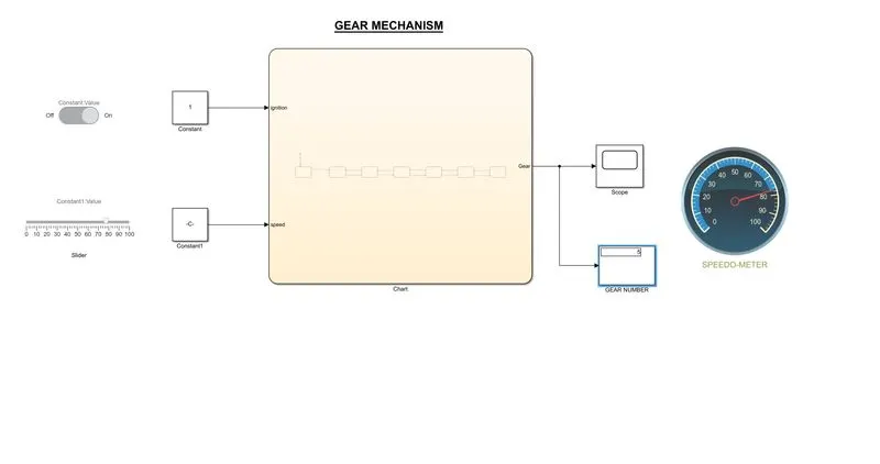
- Define ignition and speed as inputs whereas speedometer, scope, and gear number are displayed as outputs.
- Connects the chart block with constant blocks for ignition and speed inputs. Input switches connected to them are a slider switch and a slider bar to adjust variable speeds respectively. Attach lamps to observe the ON/OFF condition.
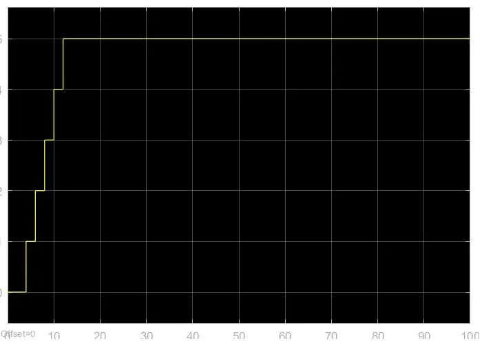
- A common scope block is connected to observe the speed numerically and obtain the output plot.
Simulink model
Conclusion
- Hence, the given problem was simulated for the gear shift mechanism and executing the state flow according to the given conditions.