Week -2
EV LIVE BATCH:-21
- Make a Simulink model of Doorbell using solenoid block with the following details:
In the above arrangement, when the switch is closed the electromagnet receives electrical power from the battery and pulls the metal arm to hit the bell producing sound.
Create a situation where the switch is closed for 2 seconds and then released. Observe the physical movement of the plunger.
Assume remaining parameters.
Ans:- According to the question, we have to create a simulink model for Doorbell using a solenoid.
Description of Doorbell using a solenoid:-
- Generally. doorbell uses a specialized electromagnet called as solenoid.
- A solenoid is just an electromagnet where the coiled wire surrounds a metal piston. The piston contains magnetically conductive metal, so it can be moved backward or forward by the electromagnetic field
- but some time, solenoid piston is made up of a iron core mounted to a non-magnetic metal bar.
- when there is no electromagnet ( at that time the the switch is not presed) then the pistion is placed at extreme left by the help of a spring.
- then when we press the doorbell then electromagnet will create in the iron core so that the pistion is moving to the right & hit with a tonebar & produce a siund as "Ding".
- as long as we keep the doorbell switch on, then the pistion is attached with the tone bar.
- then when we release the doorbell switch, then there is no electromagnet insiode the iron core so now the piston will move back to its original position by the help of spring & then produce a sound "Dong".
Description of Simulink Model:-
(A) Required blocks for this models are:-
- Pulse generator
- 2 scopes
- solenoid
- Simulink-PS coverter
- PS-Simulink converter
- battery
- switch
- electrical reference
- Mechanical translational reference
- Ideal Translational motion sensor
- solver configuration.
(B) Explaination about connections in the model:-
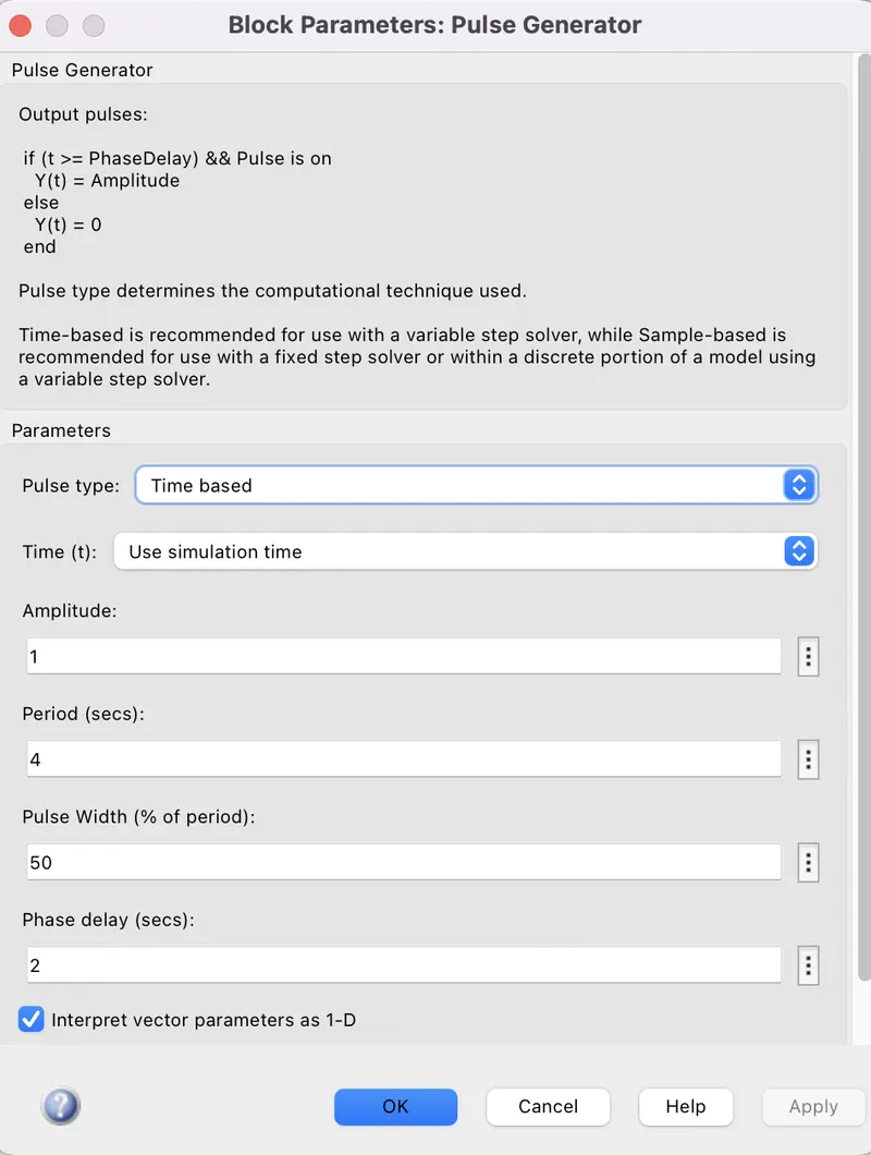
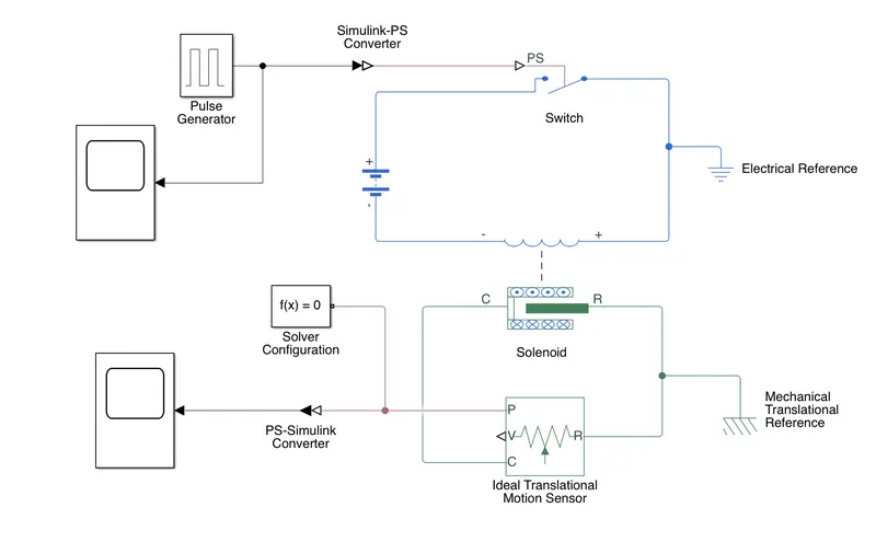
- According to the question, we have to press the doorbell for 2 sec then release the door bell for next 2 sec.
- so take the Pulse generator block & double click on that, then give the Period as 4 sec,Amplitude as 1 pulse witdh as 50% & then give the phase delay as 2 sec. & connect a scope with the pulse generator to see the waveforms.
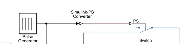
- then connect the pulse generator with simulink-PS converter block.
- then connect the output of Simulink-PS converter with the P- terminal of switch block.
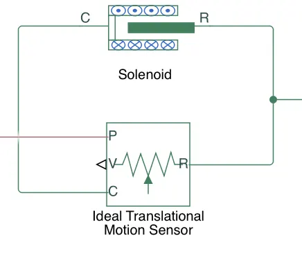
- then take the sonenoid, there are two parts such as electrical part( as an inductor image) & mechanical part. then connect the +ve terminal of battery with the -ve terminal of solenoid & vice-versa.
- then connect a electrical reference to this electrical circuit.
- then take Ideal translational motion sensor & connect the C terminal with C terminal of solenoid & R with R of solenoid.
- then connect the P- termional of Ideal rotaional motion sensor with PS-simulink converter & then conncte this with a scope.
- connect a solver configuration block with this system & connect a Mechanical Translational sensor with this Mechanical connectons.
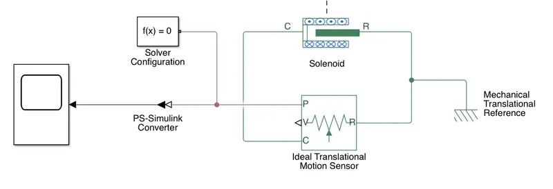
- now the Doorbrll model using a solenoid is ready for simulation.
Result:-
- when we open the scope connected with the pulse generator, then
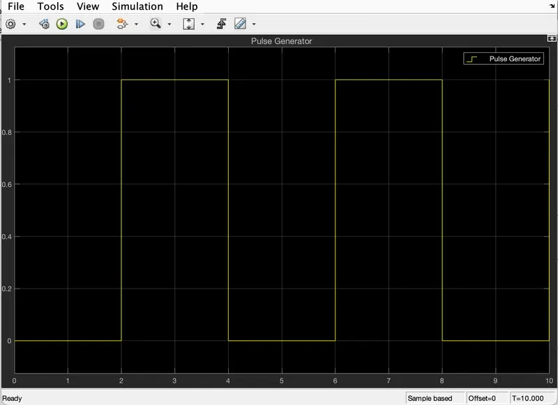
we can see that for 1st 2 sec, the amplitude of wave is 0 i.e:- at that time, the bell is not pressed as we have given the phase delay as 2sec. then for next 2sec, the bell is pressed & then for next 2 sec, the bell is released. then the process will go on. as we have given the period as 4sec & the pulse width as 50%.
- when we open the scope connected with Simulink-PS converter then we will see,
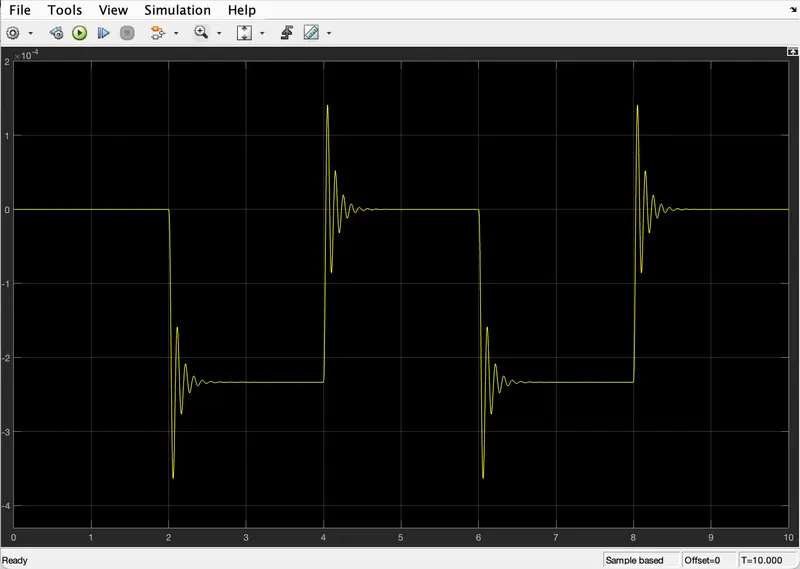
- here X-axis represents time in sec & Y-axis represents the position of plunger.
from the scope, we can clarify that for 1st 2nd sec, the bell is not pressed so there is no tue generated in the scope. but at 2 sec the bell is pressed by the user so, there is vibration has created in the bel at -2.5mm l with a sound "Ding" & the bell is pressed for 2 sec, means from 2sec to 4sec. then at 4 sec, the bell is released so that agin the vibration has created at 0mm position by producing a sound as "Dong" means now the piston has gone to it's original position. this process will occure for 2sec only. now the Ding will happen for 2 sec & the Dong will happen for next 2 sec & the process will go on.
2. Use a thermistor to sense the temperature of a heater & turn on or turn off the fan as per the below conditions:
Temperature source: 20 °C from 0 to 10 seconds, 27 °C from 10 to 30 seconds, 23 °C from 30 to 50 seconds
Fan conditions: ON if the temperature above 25 °C, OFF otherwise
Ans:- According to the question, we have to sense the temperature of a heater by the help of a thermistor & according to the value of temperature the fan will automatically turn on & turn off.
Thermistor:-
- Thermistor is a semiconductor device which has a resistance more then a conductor & less than a insulator.
- it is a type of device whose resistance changes with the change in temprerature.
- there are mainly two types of thermistor present such as Positive temperature co-efficient (PTC) & Negative temperature co-efficient (NTC)
- PTC is a type of themistor whose resistance increases with the increase in temperature but Resistance of NTC thermistor decreases with increase in temperature.
- Themistors are made up in such a way that they can't operate in extremely hot & extremely cold condition.
Required Blocks:-
- Signal builder
- Controlled temperature source
- Thermistor
- Resistor
- DC voltage source
- voltage sensor
- electrical reference
- solver configuration
- Switch block
- Controlled voltage source
- DC motor
- Ideal rotational motion sensor
- Mechanical rotational reference
- 3 scopes
- 2 Simulink-PS converters
- 2 PS-Simulink converters
- 2 constant blocks
- display block
Description about the Model:-
- take a signal builder block 7 then insert a new constant signal. then delete the 1st signal & then give the signal name as Temp which will represent the varrying temperature w.r.t time
- accroding to the question, there are 3 different temperatures in different time period such as, 20 °C from 0 to 10 seconds, 27 °C from 10 to 30 seconds, 23 °C from 30 to 50 seconds
- as we take Simulink-PS converter which to convert the simulink signal into physical signal in which we can't use the degree celcious as input so, we have to convert the degree celcious into kelvin.
- we know that, 1 degree celcious = 273.15 Kelvin so,
20 deg celcious = 273.15+20 = 293.15 Kelvin
27 deg celcious = 273.15+27 = 300.15 Kelvin & 23 deg celcious = 273.15+23 = 296.15 Kelvin
- according to the above information we have to change the Time axis limit from 0sec to 50 sec & the Y-axis limit from 280 to 310 which represents the temperature in kelvin.
- then the signal builder will contain the time variant temperature signal as
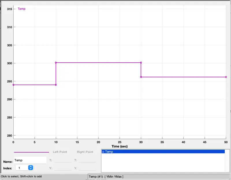
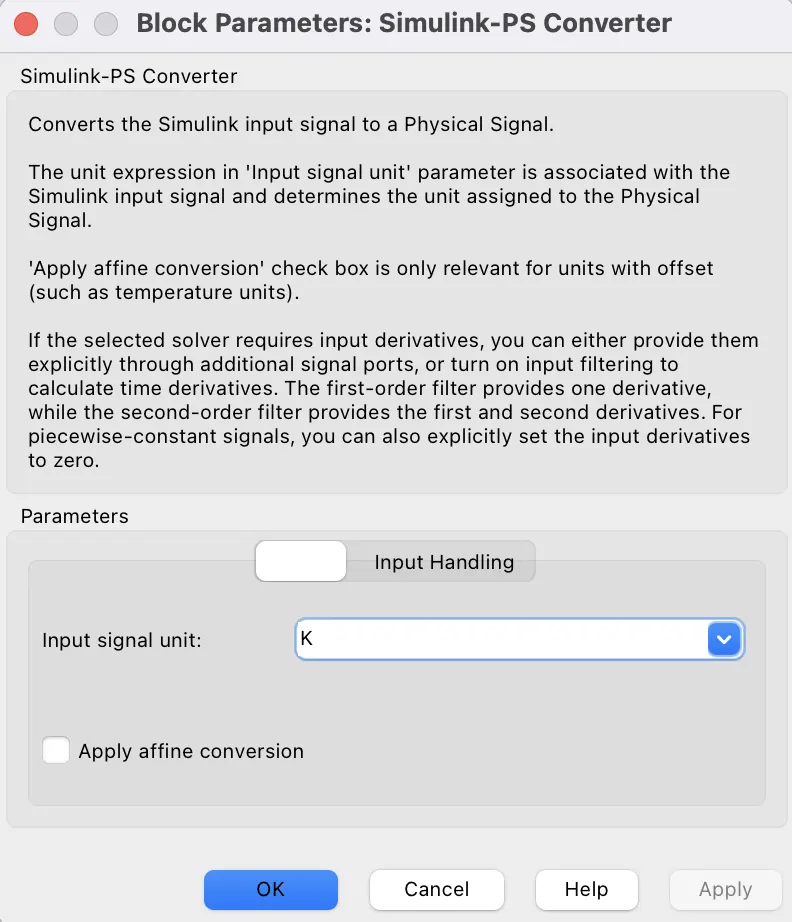
- Then connect the signal builder with the simulink-ps converter block to convert the simulink signal into physical signal. here we have to choose the unit of that converter block as K means kelvin.
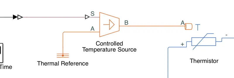
- then connect that converter block with the P-terminal of Controlled temperature source. & A port is connected with a Thermal reference & the B port is connected with the A port of Thermistor which is a NTC type thermistor.
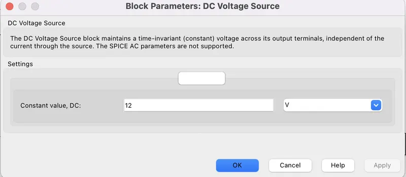
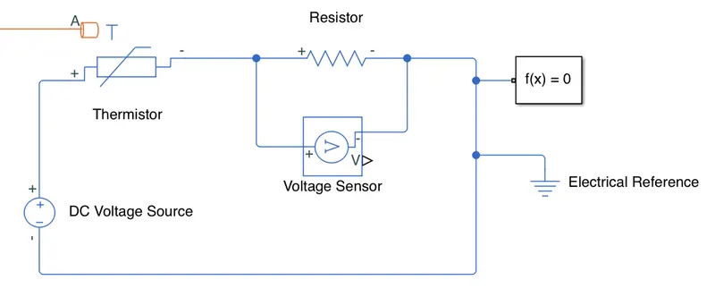
- then connect the +ve terminal of thermistor with +ve terminal of DC voltage source ( we have to take the voltage of DC voltage source as 12 Volt) & the -ve terminal of that thermistor with +ve terminal of resistor.
- then connect -ve terminal of DC voltage source with the -ve terminal of resistor.
- then connect a voltage sensor accross the resistor.
- connect a solver configuration & a electrical reference with this electrical system.
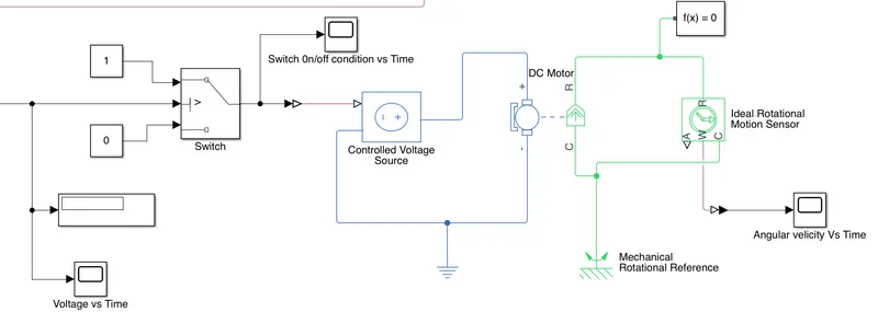
- as we have two conditions for a fan i.e:- either ON or OFF conditions. so take two constant block & give values as 1 & 0.
- then connect constant block of 1 value with the 1st input of a switch block & constant block of 0 value with the 3rd input of thar switch block. value 1 means the switch is ON & value 0 means the switch is OFF.
- the middle port of the switch block is control input i.e:- if the input given to the control input statisfy the desired condition then the switch block will allow the 1st input other wise the 2nd input.
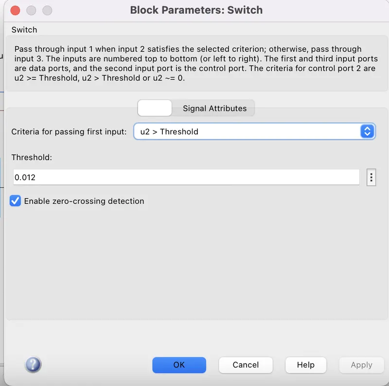
- so give the Threshold value for the switch block as 0.012 which is the voltage accross the resistor connected with the thermistor at 25 deg celcious temperature & then choose the condition as u2>Threshold.
- as switch is not a physical block so connect a PS-simulink converter with the control input which is coming from V-port of Voltage sensor block.
- then again we have to turn on or off a fan which is a phsical block so again connect a simulink-ps converter with the output of switch block.
- here we have choose DC motor instead of a fan.
- so connect the simulink-ps converter with controlled voltage source & then connect the -ve terminal of controlled voltage source with -ve port of DC motor & vice-versa.
- then take a Ideal rotational sensor with the DC motor.
- then connect a solver configuartion & a Mechanical rotational reference with this connections.
- now connect scopes with appropriate blocks to see the out put results as follows:-
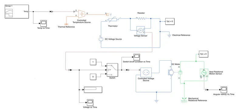
- now all the connections are completed so the model is ready foe simulation. & the model looks like as
Result:-
- as we have taken the Maximum time as 50sec, so when we run the model for 50sec then we can observe all scopes such as Temperature vs time, Switch ON/OFF condition vs Time & Angular velocity Vs Time.
- when we open the Temperature Vs Time scope then we got,
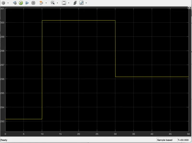
Here X-axis represents the time in second & Y-axis represents the temperature in Kelvin. we can see that from 0sec to 10sec, Temperature is 293.15 kelvin means 20 degree celcious. from 10 to 30 sec, temperature is 300.15 Kelvin means 27 degree celcious & from 30 to 50 sec, temperature is 296.15 Kelvin means 23 degree celcious.
- when we open the Switch ON/OFF condition Vs time scope then we got,
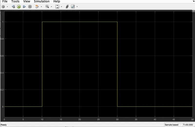
here X-axis represents time in second & Y-axis represents values comes from switch block i.e:- either 1 or 0. we cam clarify that, from 0 to 10 sec when the temperature is 20 degree celcious or 293.15 kelvin then switch is in OFF condition means 0 value. then from 10 to 30 sec, when the temperature is 300.15 kelvin or 27 degree celcious then the switch is ON or the value is 1 & from 30sec to 50 sec,when the temperature is at 23 degree celcious then switch is in OFF condition.
That means from this graph, we can conclude that, when the temperature is above 25 degree celcious then the switch is in ON condition otherwise switch will be in OFF condition.
- then when we open the Angular velocity vs time scope, then we got
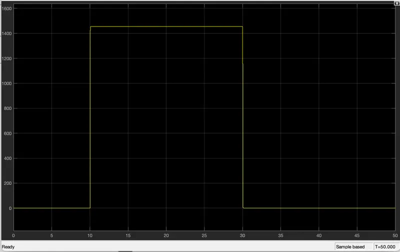
here X-axis represents Time in sec & Y-axis represents angular velocity of the DC motor in rpm.
we can see that, from 0 to 10 sec when the temperature is at 20 degree celcious then there is no angular speed of the DC motor means the motor is in OFF condition. from 10 to 30 sec, when the temperature is at 27 degree celcious then angular speed of the DC motor is approximately about 1430 rpm means the motor is in running condition but again from 30 to 50 sec, angular speed becomes 0rpm means motor is in OFF condition at that time temperature is 23 degree celcious or 296.15 kelvin.
- finally we can conclude from all scope results that, the Fan will active when the temperature is above 25 degree celcious or 298.15 kelvin
- hence we sucessfully create a model using a themistor to sense the temperature of a heater & turn on or turn off the fan.