Week - 4
AIM :
To Implement control logic of a “washing machine” using Stateflow as per given sequence of simulink modukle and Gear shift” logic simulink display the output.
1)
- Implement control logic of a “washing machine” using Stateflow as per given sequence:
- If the power supply is available, the system gets activated
- If the Water supply is not available, stop the process & indicate through LED
- Soaking time should be 200s followed by Washing time of 100s.
- Then rinsing happens for next 20s & dryer runs for 50s
After all the processes have completed turn on the finished LED
procedure :
STATEFLOW MODULE AND CONTROL LOGIC :
The stateflow module is the simuling flow chart methode. this is the block diagram of flow chart and state transison tables and truth table is used in matlab and simulink dray the design of chart table module.
All the stateflow and control logic is used in truth table and flow chart methode.
"Washing machine” control logic working in simulink flow chart :
- If the power supply is available, the system gets activated
- If the Water supply is not available, stop the process & indicate through LED
- Soaking time should be 200s followed by Washing time of 100s.
- Then rinsing happens for next 20s & dryer runs for 50s
Condition of control logic is used in stale flow charts is working principle of wasing machine :
SOAKING :
This is the wasing machine fill the cloths and water using 45 mint of wasing the cloths. the wasing time is sum detergent poweder is use fill the water of machine.
WASING :
This wasing is the water is fill and cloths is move and rotated cleane. power is on stage working in process state. power on stage green colore LED light bllinging.
RISING :
Rising is the clean water using cleaning all cloths and remove the soap and powder mixed water is clean after freesh water is using clean the cloths.
DRYER :
Dryer is the sum heat air flow the cloths after all the clothes is fully dryar stage.
finly complete the process of this all stae of functions in end.
first fill the water and clothes, next sum sop power is mixed the water after powre on the wasing machine.
next water is low or watre is stop power is automatlicy stoped.
STATE FLOW MODUL :
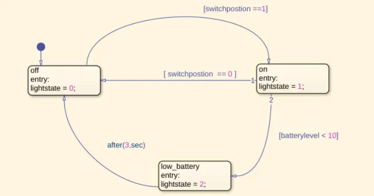
this state flow module of logic is battery os off lightstate is ==0 is power is off. next move on other block is switch position is high state block On lightstate ==1 , battery is lightste=2 working
WASING MACHINE CONTROL LOGIC :
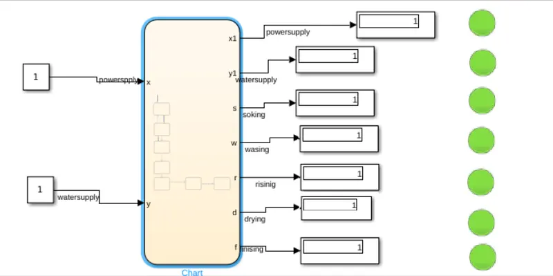
Controle block is simuling charfical module of diadram in the starting, power supply source,
water supply and soaking, wasing,rising, drying, finly finising is tall the avlible. all state is on condition wasing machine is working other waice machine off state. time cycle is soking 200 sec ,wasing 100 sec , rising 20sec,
draying 50 sec is working in the wasing machine.
2. Make a Simulink chart for the “Gear shift” logic as per below conditions:
Speed Range(kmph) Gear
0 to 15 1
16 to 25 2
26 to 40 3
41 to 60 4
Above 61 5
Give speed input while the simulation is running & display the gear number.
the “Gear shift” logic :
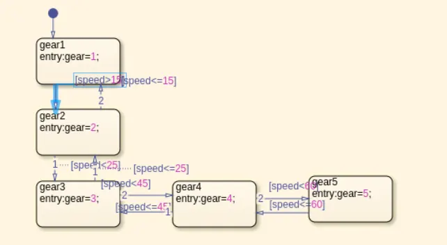
gear logic block of chart diadram is uaing to the value of start to gear1 in to gear5 change time to incresing the speed and decrising speed.
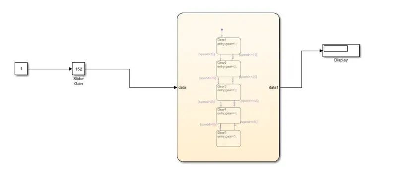
thios gear concept also completede and result in the simulik chart of statflow concept. the speed is change gear speed will be incresing.
conculation :
to finsh the two concept of simulink stale flow and condrol logic results in waching machine and gear shift logic.