Week - 4
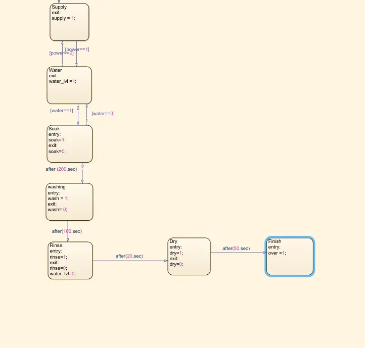
Implement control logic of a “washing machine” using Stateflow as per given sequence:
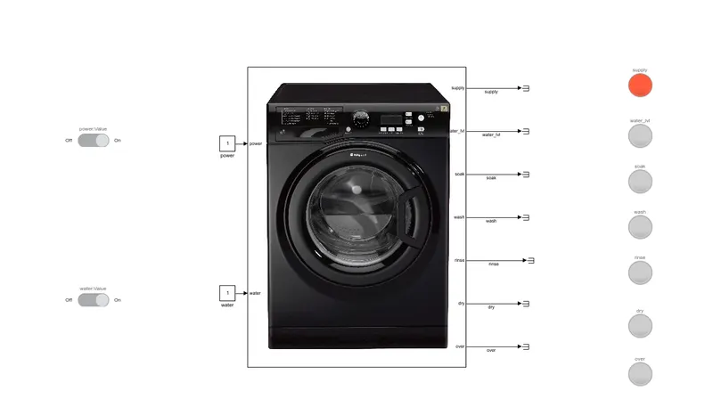
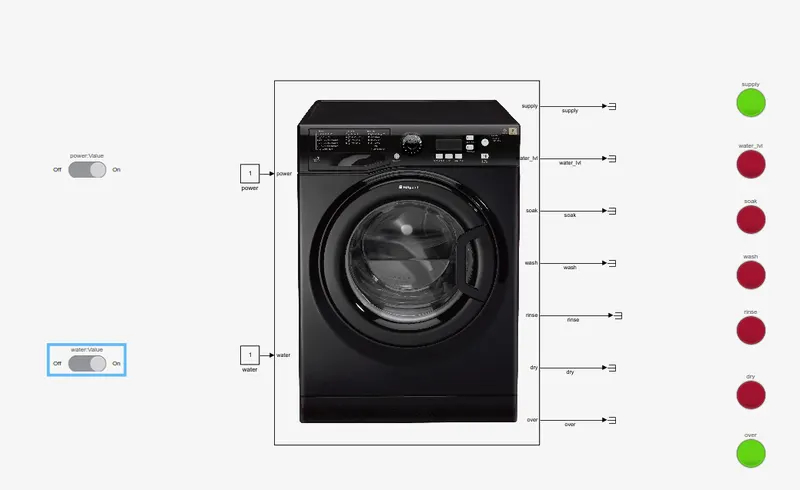
The simulink model and stateflow for the implemented system is shown below
Conditions
1. Power supply and water is given as input via a toggle switch linked to a constant whose value changes from ON to OFF.
Power = 0(OFF), water = 0(OFF) condition is being highlighted using lamp, RED colour.
The whole system will not depend on any other value and system will be in shutdown condition.
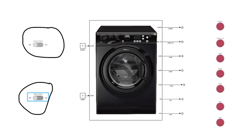
POWER ON condition is being highlighted using lamp, GREEN colour for ON condition.
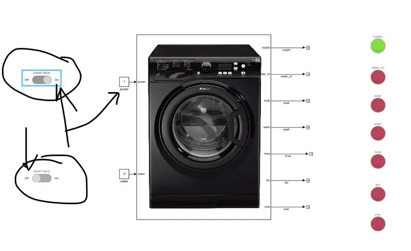
2. Now the whole system will depend on value of water supply for further operation.
If water supply is being cut down or unavailable = 0, the system will not be working. This condition is simulated again by the use of toggle switch connected to a constant value.
So, if with power supply in state 1, water supply being in OFF state our system won’t function.
3. If both power supply and water is available the system will function according to design.
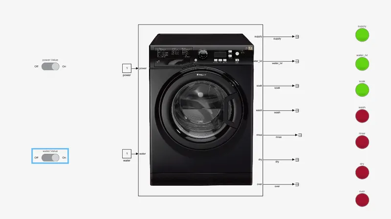
Now soaking will take for 200 sec,during soaking LED will be turned to GREEN
4. And after soaking for 200 sec, so the indicator of soaking will be turned to GREEN from RED and next stage of washing, needs 100 sec so the LED will be turned to GREEN.
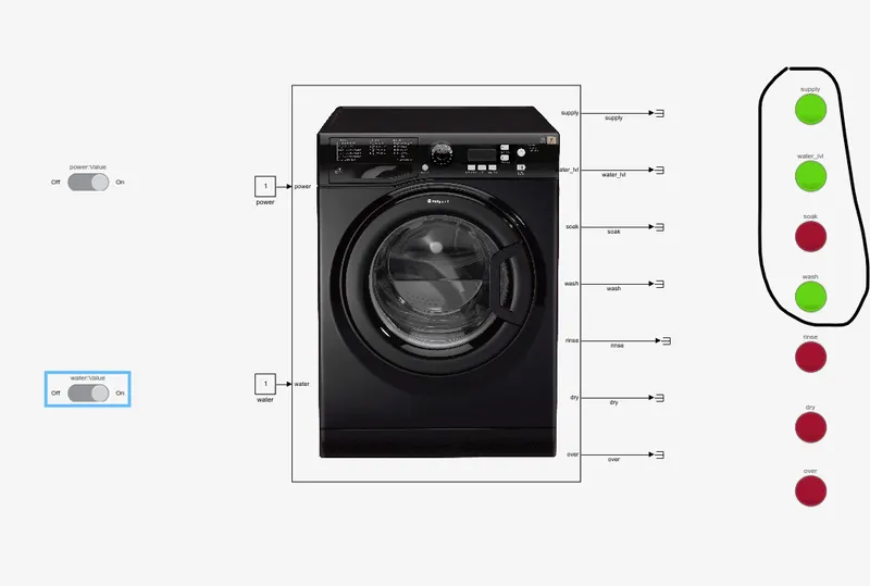
5. After 100 sec washing will be over and LED will be turned to GREEN from RED and next stage of rinsing, needs 20 sec so the LED will be turned to GREEN.
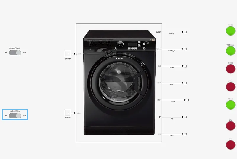
6. After 20 sec rinsing will be over and LED will be turned to GREEN from RED and next stage of drying needs 50 sec so the LED will be turned to GREEN.
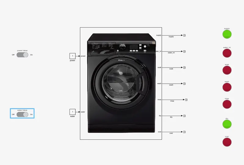
7. After 50 sec drying will be over and LED will be turned to GREEN from RED and the process will be ovwe so the LED of OVER will be turned to GREEN.
Make a Simulink chart for the “Gear shift”
1.The system is implemented starting from ignition on or off condition.
2.If the ignition is on then only gear shift mechanism will work, else it won’t.
3.According to the requirement depending upon the speed criteria the shift in gear and the state flow has been designed.
The implemented system is as shown below.
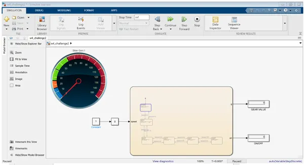
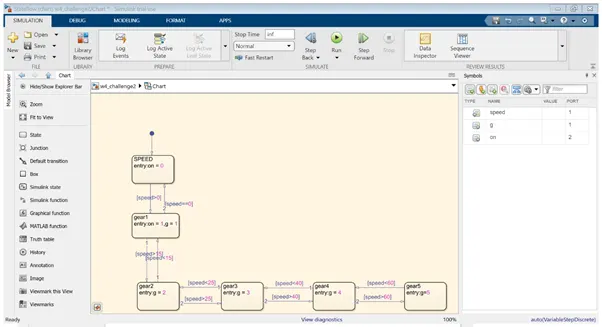
4. The speed variation is implemented by using a gain slider and the change of value is displayed using a circular gauge from dashboard.
5.The gain slider is having an input as constant with value = 1. As the slider changes,value of speed is also varies and depending upon the value of speed the value of gear is displayed on to the display..
So with variable speed , we can see the change in circular guage , gear value and on/off condition from display
CASE1 - When speed in is between 0 to 15
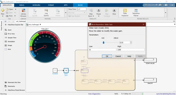
- Slider value is at 12,
- in gauge speed displayed is 12.
- Gear value is 1 and it’s in ON condition.
- Its visible from the chart, that the state has moved to 2nd condition highlighted with blue border.
CASE 2 - When speed in is between 16 to 25
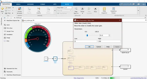
- Slider value is at 21,
- speed displayed is 21.
- Gear value is 2.
- Also, its visible from the chart, that the state has moved to 3rd condition highlighted with blue border.
CASE 3 -When speed in is between 26 to 40
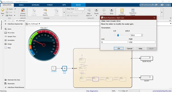
- Slider value = 39,
- gauge speed display= 39.
- Gear value = 3 and it’s in ON condition.
CASE 4 -When speed in is between 40 to 60
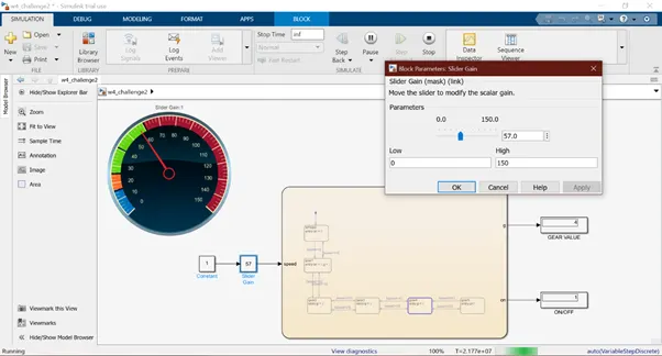
- Slider value is at 57, from gauge, the speed display = 57.
- Gear value= 4 and it’s in ON condition.
- The state has moved to 5th condition highlighted with blue border.
CASE 5 -When speed is above 60

- Slider value = 100, gauge display= 100.
- Gear value = 5 and it’s in ON condition.
- Also, its visible from the chart, that the state has moved to 6th condition highlighted with blue border.