Project
AIM - This projects aims at building a simulation model with continous variable transmission for BAJA ATV.
The project has been done in two ways .
1) By using combination of constant and dashboard knob block for giving brake and throttle values as input.
2) By using signal builder block for giving brake and throttle values as input
--------------------------------------------------------------------------------------------------
Method 1 - using Dashboard
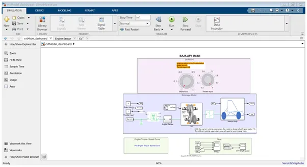
- Dashboard have been used for giving the input values of torque and brake. Brake and torque are connected as knob from dashboard to the constant with value 0 and 1 respectively.
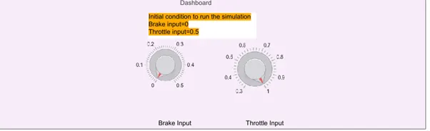
- The value of each can be varied from 0 to 1 using the dial which will give variable input and it will be more realistic in nature.
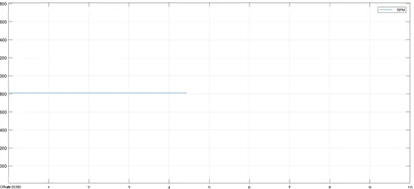
- We are using dashboard for varying the value the simulation runs for infinite time. Also as the values of variable speedVector and torqueVector are not for infinite time the graphs obtained after simulation gives graph with half way stopped values.
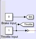
In contrast to previous simulation where we have used signal builder, here we have used dashboard.
The brake input signal & throttle input signal are then connected to the goto block , also the goto block is connected to the generic engine block via Simulink to PS converter.
2) Generic engine block
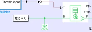
- The torque from signal builder block is given as input to the engine block. Apart from that, port B is being connected to the solver configuration and the mechanical rotational reference.
- This engine block’ parameter in engine torque, has two values – speed vector and torque vector.
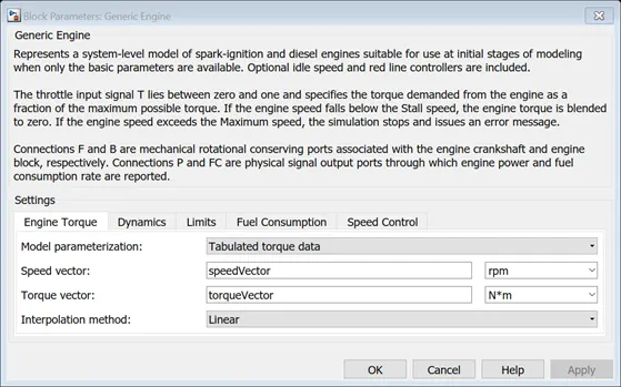
- Instead of giving its value directly, a variable has been assigned to both with the names speedVector & torqueVector. These values have been provided from base workspace in the form of imported excel sheet.
- The port F is connected to the engine sensor’s port F.
3) Engine sensor
- This block is basically an ideal rotational motion sensor, used for measuring angular velocity.
- Output port F from previous block is given as input to the Port R of the rotational motion sensor.
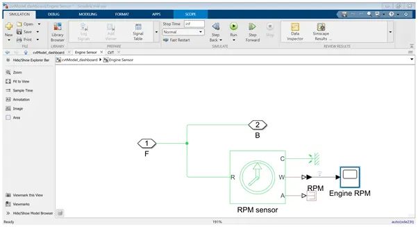
- The output ports of the block C are connected to rotational reference,
- Port A is connected to terminator and Port W is connected to the scope for viewing the velocity in rpm via Simulink to PS converter.
4) CVT block - This block is basically a combination of inertia, variable gear ratio and rotational motion sensor.
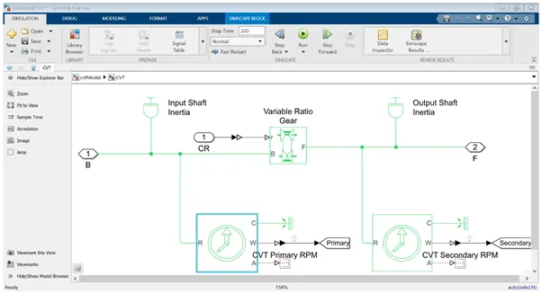
The cvt ratio of variable value generated from the signal builder is given to the variable gear ratio.
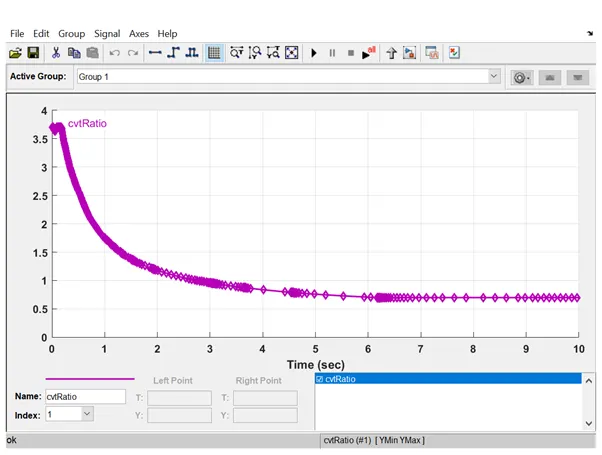
- It is input to the variable gear ratio.
- The output from the variable gear ratio is given as input to the secondary rotational sensor and to the port B of simple gear ratio.
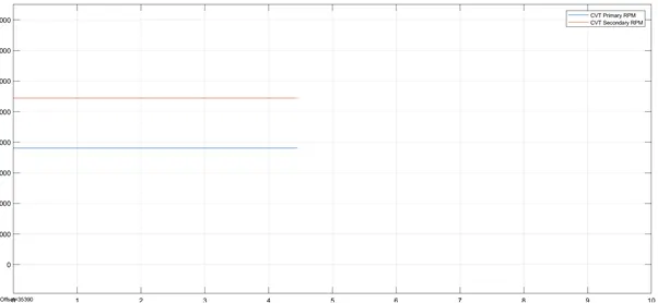
- Also the angular velocity from both primary and secondary sensor are sent to scope via goto block.
5) Vehicle Body
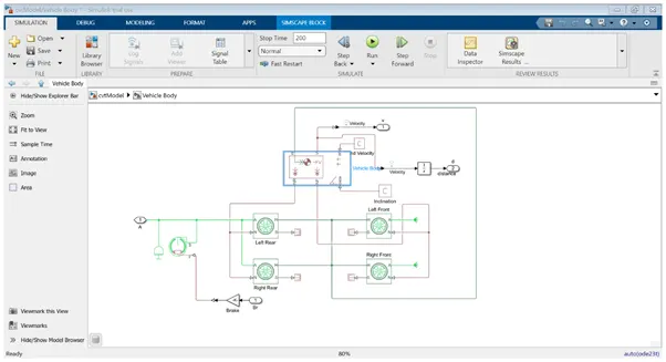
As seen from the figure, vehicle body is combination of vehicle body block, tire, integrator, inertia and double shoe break.
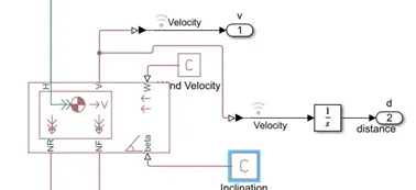
- Port H - mechanical translational conserving port associated with the horizontal motion of the vehicle body which is connected to port H of all four tire blocks.
- Port NF, and NR - physical signal output ports for vehicle front and rear normal wheel forces, which in turn connected to port N of front wheels and port N of rear wheels respectively.
- Port V - output port for vehicle velocity which is connected to output port 1 the scope for observing the vehicle speed and it’s also connected to the integrator to get the distance covered by the vehicle which is in turn connected to the port 2.
- Port S - output port that reports the tire slip, all port S are connected to terminator.
- Port A - rear wheel are powered by the output port F of simple gear ratio block and port A of the front wheels are connected as free end.
- Port W and beta - physical signal input ports corresponding to headwind speed and road inclination angle, respectively and these ports are connected to PS constant with value 1 each.
- So the output of vehicle body is plotted using scope.
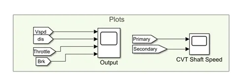
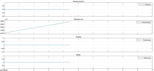
Values of throttle & brake is constant the velocity is constant and distance covered is a ramp function.
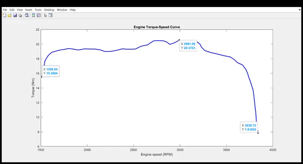
- The torque and speed curve from simscape scope, the value of rpm is 1508 and the corresponding torque is 15 Nm
- gradual increase in each value to torque value of 20 Nm and then reduces to torque value of 7 Nm with torque value of around 3840 Nm.
--------------------------------------------------------------------------------------------------------------------------------------------------
Method 2 - using signal builder block
This report gives a detailed explanation regarding the simulation work for CVT.
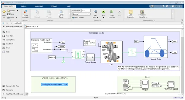
In this model, the various components used are
1) Signal builder - This block is used to give the two inputs to the engine – brake and throttle.
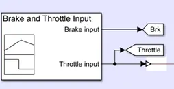
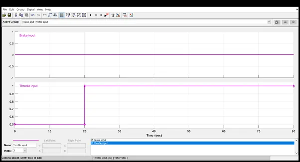
- From above, it shows two inputs - brake, whose value is kept 0 throughout and value of second signal throttle, which changes from 0.5 to 1 at the 20th sec and then it remains 1 throughout.
- Brake input signal & throttle input signal are then connected to the goto block , also the goto block is connected to the generic engine block via Simulink to PS converter.
2) Generic engine block
- Torque from signal builder block is given as input to the engine block.
- Port B is being connected to the solver configuration and the mechanical rotational reference.
- Engine block parameter in engine torque, has two values – speed vector and torque vector.
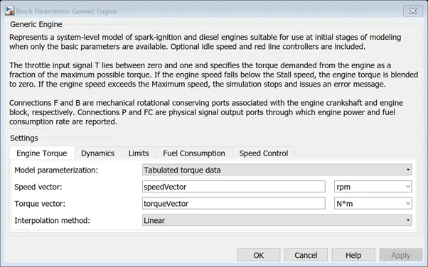
- Instead of giving its value directly, a variable has been assigned to both with the names speedVector & torque Vector.
- The values have been provided from base workspace in the form of imported excel sheet.
- The port F is connected to the engine sensor’s port F.
3) Engine sensor - This block is basically an ideal rotational motion sensor, used for measuring angular velocity. Output port F from previous block is given as input to the Port R of the rotational motion sensor.
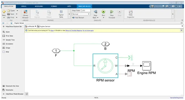
The output ports of the block C are connected to rotational reference, port A is connected to terminator and port W is connected to the scope for viewing the velocity in rpm via Simulink to PS converter.
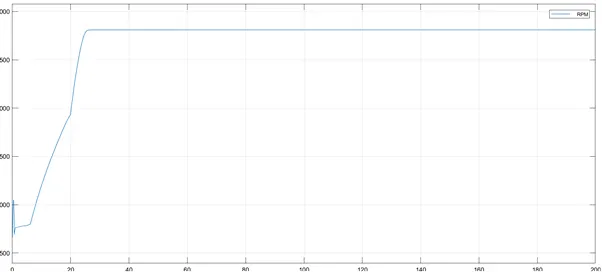
Graph shows the rotational velocity in rpm.
When compared to the torque input from signal builder , as the torque value changes from 0.5 to 1, the rpm value also changes and becomes constant after the torque value is constant at value 1.
4) CVT block - This block is basically a combination of inertia, variable gear ratio and rotational motion sensor.
- The output of engine block is given as input to the gear ratio and the primary rotational sensor.
- The cvt ratio of variable value generated from the signal builder is given to the variable gear ratio.
- This signal is given as input to the variable gear ratio.
- The output from the variable gear ratio is given as input to the secondary rotational sensor and to the port B of simple gear ratio.
- The angular velocity from both primary and secondary sensor are sent to scope via goto block.
5) Vehicle Body
Vehicle body is combination of vehicle body block, tire, integrator, inertia and double shoe break.
- Port H is the mechanical translational conserving port associated with the horizontal motion of the vehicle body which is connected to port H of all four tire blocks.
- Port NF, and NR are physical signal output ports for vehicle front and rear normal wheel forces, which in turn connected to port N of front wheels and port N of rear wheels respectively.
- Port V is the output port for vehicle velocity which is connected to output port 1 the scope for observing the vehicle speed and it’s also connected to the integrator to get the distance covered by the vehicle which is in turn connected to the port 2.
- Port S is an output port that reports the tire slip, all port S are connected to terminator.
- Port A of rear wheel are powered by the output port F of simple gear ratio block and port A of the front wheels are connected as free end.
- The double shoe brake it’s force from the brake from block which gets the signal from signal builder block via Simulink to PS converter, as described earlier.
- Port W and beta are physical signal input ports corresponding to headwind speed and road inclination angle, respectively and these ports are connected to PS constant with value 1 each.
So the output of vehicle body is plotted using scope.
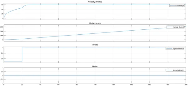
From the scope it is clear that with brake value = 0 and torque value from 0.5 to 1,
we can infer that with brake = 0 the distance value is increasing and with constant throttle after reaching the value = 1 the velocity is also constant.
Next graph is the response from primary and secondary shaft respectively.
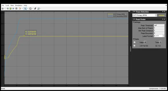
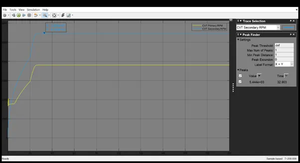
We can observe the highest value attained by primary shaft is 3810 rpm and secondary achieves the value of 5444 rpm.
- Now from the torque and speed curve from simscape scope, we can deduce that the value of rpm is 1508 and the corresponding torque is 15 Nm followed by gradual increase in each value to torque value of 20 Nm.
- Then reduces to torque value of 7 Nm with torque value of around 3840 Nm.