Week - 4
Aim:
- Implement control logic of a “washing machine” using Stateflow.
Objective
- If the power supply is available, the system gets activated
- If the Water supply is not available, stop the process & indicate through LED
- Soaking time should be 200s followed by Washing time of 100s.
- Then rinsing happens for next 20s & dryer runs for 50s
After all the processes have completed turn on the finished LED.
Theory:
Stateflow (developed by MathWorks) is a control logic tool used to model reactive systems via state machines and flow charts within a Simulink model. Stateflow uses a variant of the finite-state machine notation established by David Harel, enabling the representation of hierarchy, parallelism and history within a state chart.
Stateflow is generally used to specify the discrete controller in the model of a hybrid system where the continuous dynamics (i.e., the behavior of the plant and environment) are specified using Simulink.
Specific applications for Stateflow include:
- Mode logic, where each discrete mode of a system is represented by a state
- Fault management, where the Stateflow chart is used to control how the system responds to faults and failures within a system
- Task scheduling, where the Stateflow chart is used to schedule when specific tasks occur, either within the Stateflow chart or within the overall Simulink model.
Technologies and developments in the field of household appliances are constantly surprising. Engineers come up with all sorts of innovations in order to attract the attention of the buyer to their creation. Once the very appearance of a washing machine seemed like a miracle, because what could be simpler - laid the laundry and powder, pressed a button, and after an hour you can get clean things, and at this time you can cook dinner, or lie on the couch.
But progress does not stop there, cars constantly provide new functions, for example, fuzzy logic, eco bubble, stream wash, drying and others. It is sometimes very difficult to keep track of technologies and understand them.
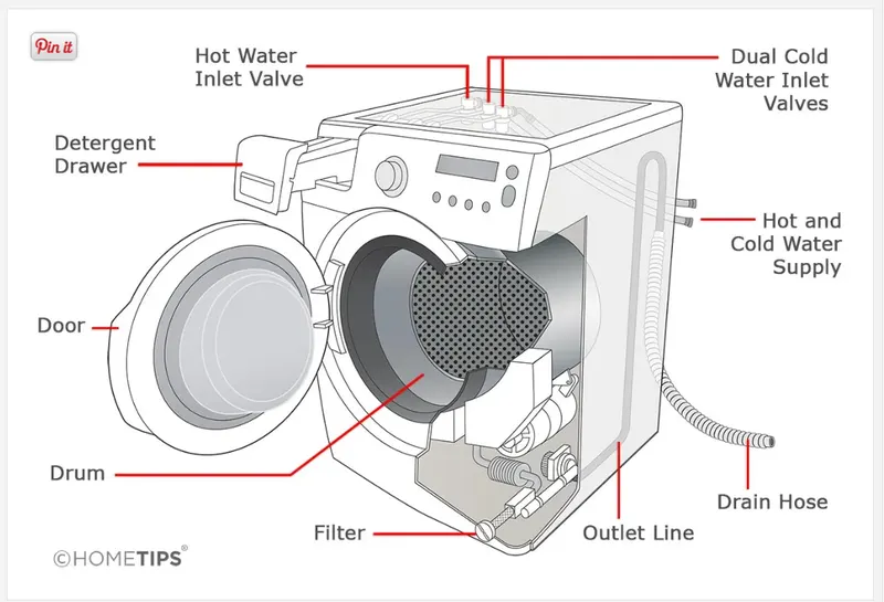
The anatomy of a washing machine with a cutaway illustration of its parts
There are a few variations in clothes washers—some load from the top and others load from the front—but all washing machines are basically big tubs that fill up with water, agitate to scrub clothes, and spin to wring out the water.
Of course, in addition to these basic functions, they may have any number of sophisticated settings including water temperature controls, steam options, and electronic timers.
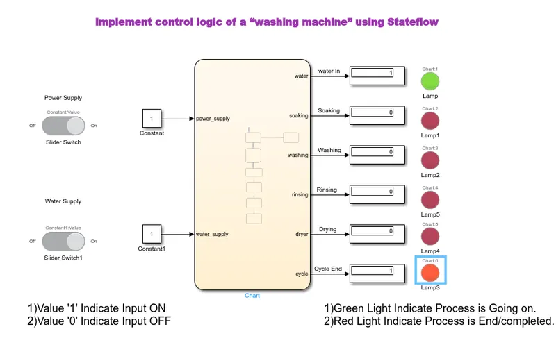
Control Logic of Washing Machine
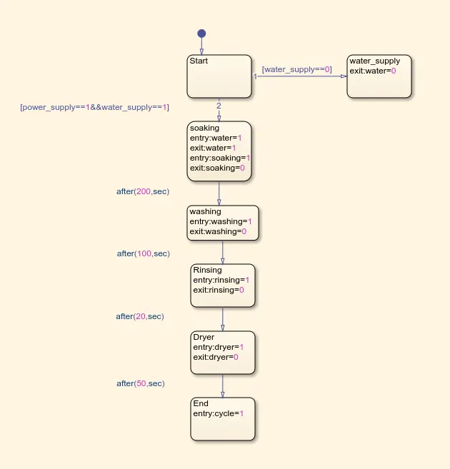
Flow Chart
Parameters
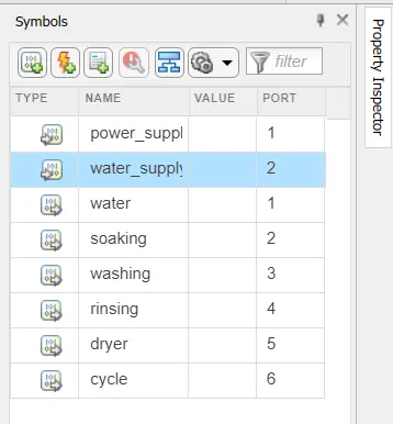
Input Parameters: 1 Power Supply,2 Water Supply.
Output Parameters:1 Water in,2 Soaking,3 Washing,4 Rinsing,5 Drying,6 Cycle End.
- In the above control logic block diagram starting state is created with two transition conditions, 1 is power supply = 1 and 2 is water supply = 1. That means both water and power supply are on.
- The second state is soaking, in this state the water supply is required so we give water supply. After completion soaking and
water supply are off. As per given condition we gave time 200 sec for this process with the help of transition condition. - The third state is washing, in this state only washing is done with already available water in washing machine this process is
took 100 sec time per given transition condition. And water drains from the machine. - The fourth state is raining, in this process repeated washing has happened so we required water supply here. The water supply is off after 20 sec and rinsing state also done as per given transition condition.
- The fifth state is dryer, in this process the cloths are dry in 50 sec as per given transition condition after completion of process dryer would off with the help of sate condition.
- In this model we use stateflow chart to create control logic for washing machines. We used two switches to operate power and water supply.
- Lamps are used to watch power and water supply state which is on or off. The switch and lamp are connected to constant block. Constant block is connected with control logic.
- All process ports are connected with display and display is connected with lamp to watch the process of washing machine with respect to given time.
- After completion of all process cycle light would appear Red. We run this simulation for 600 sec.
Results
Result of control logic of washing machine is shown in above.we get the satisfactory outputs.
======================================================================================================================================================
AIM
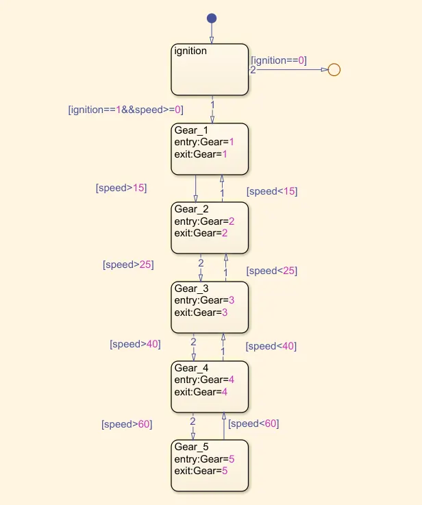
2.Make a Simulink chart for the “Gear shift” .
conditions:
Speed Range(kmph) Gear
0 to 15 1
16 to 25 2
26 to 40 3
41 to 60 4
Above 61 5
Give speed input while the simulation is running & display the gear number.
Gear Tranmission
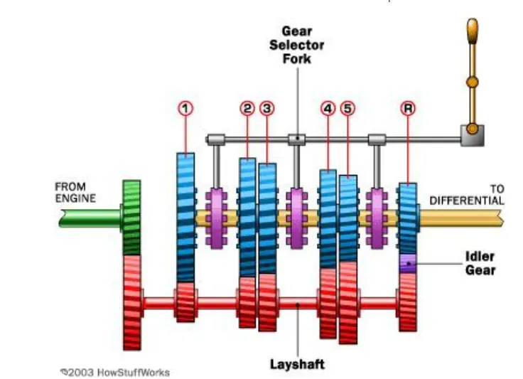
Gearbox Working Principle:
A Gearbox consists of various gears, synchronizing sleeves, and a gear-shifting mechanism fitted inside a metal housing. The metal housing, usually made of aluminum/iron casting, accommodates all the gears. The gearbox is a part of the ‘transmission’ system as the gears play an important role in transmitting the engine power to the wheels.
What is Transmission?
All the drive-train components that help transmit the engine power to the wheels are a part of the ‘Transmission’ system. Of which the gearbox is an integral part. These components include the clutch, gearbox, couplings, propeller shaft, axle shafts, and differential. In general, ‘Transmission’ usually refers to the car’s gearbox. However, some car designs integrate the gearbox and differential assembly into a single unit called ‘Transmission’ or ‘Trans-Axle.’
Control Logic(Flow chart)
Parameters:
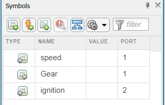
Input: Ignition,Speed.
Output: Gear
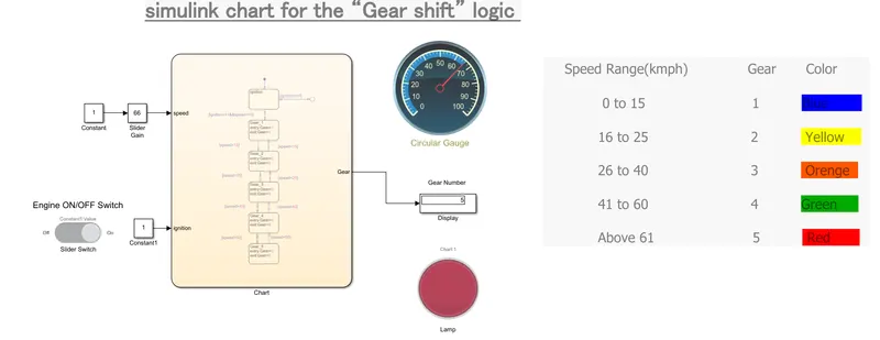
Model
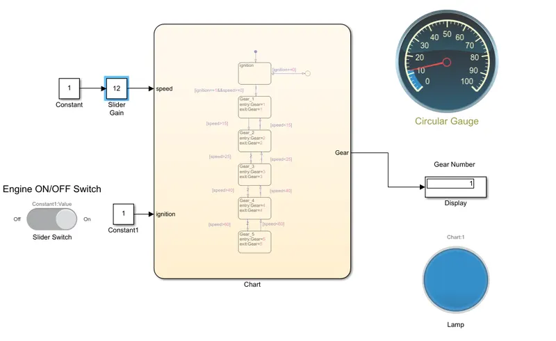
1St Gear
Speed Range= 0- 15kmph
Input Speed=12 kmph
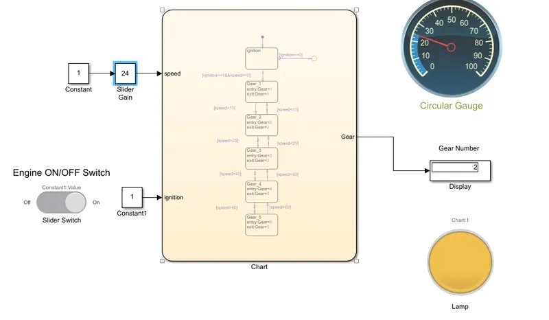
2nd Gear
Speed Range= 15- 25kmph
Input Speed=24 kmph
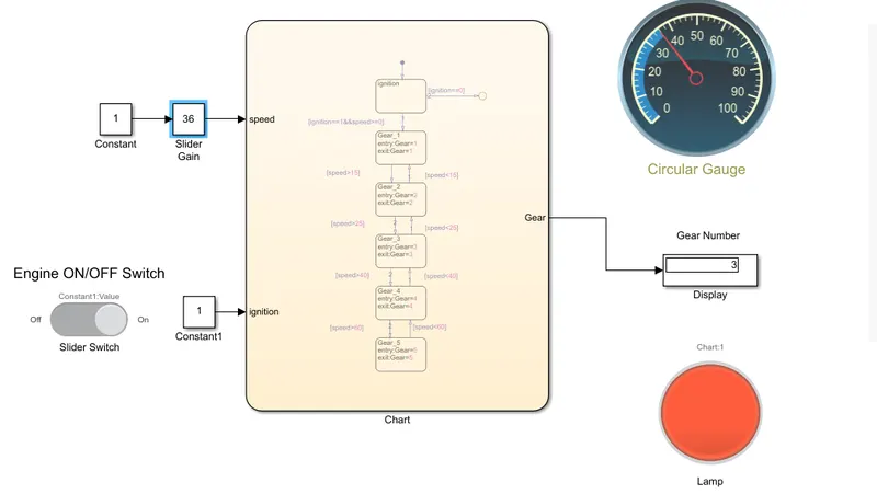
3rd Gear
Speed Range= 26- 40kmph
Input Speed=36 kmph
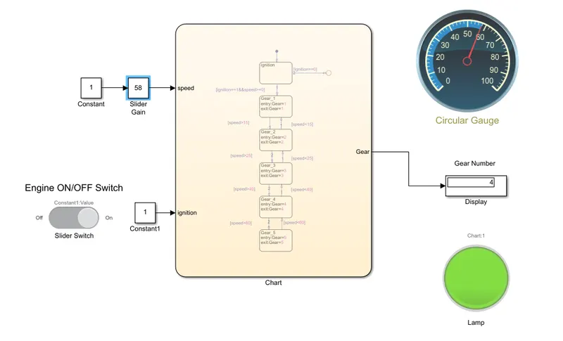
4th Gear
Speed Range= 41- 60kmph
Input Speed=58 kmph
5th Gear
Speed Range= above 61kmph
Input Speed=80 kmph
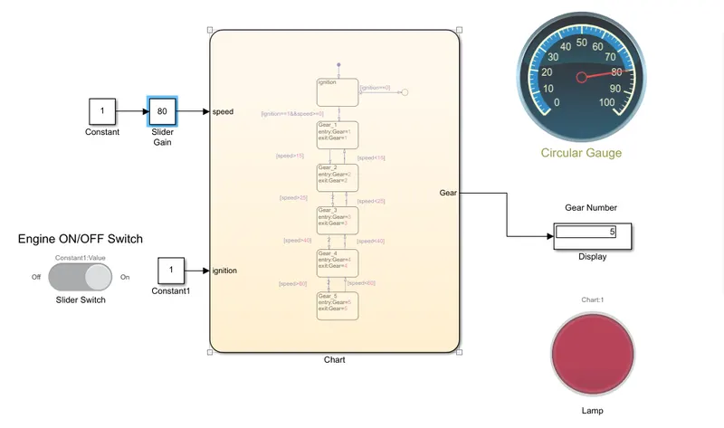
In the above model we used slider gain block for variable speed and connect to control logic stateflow block. Display block is connected to control logic to see which gear is running and also used lamp for better graphical presentation to user.
Conclusion
- Implement control logic of a “washing machine” using Stateflow as per given sequence.
- Give speed input while the simulation is running & display the gear number.