Week - 4
Q1. Implement control logic of a “washing machine” using Stateflow as per given sequence:
- If the power supply is available, the system gets activated
- If the Water supply is not available, stop the process & indicate through LED
- Soaking time should be 200s followed by Washing time of 100s.
- Then rinsing happens for next 20s & dryer runs for 50s
After all the processes have completed turn on the finished LED
Ans:
The complete model of the washing machine is as follows:
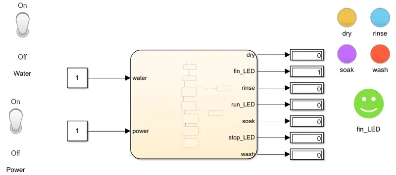
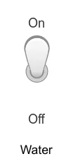
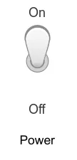
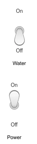
A Toggle switch is provided for power and water as can be seen on the left side.
The operation phases are denoted by the lamps on the right side.

The Finish lady is represented by green Lamp.

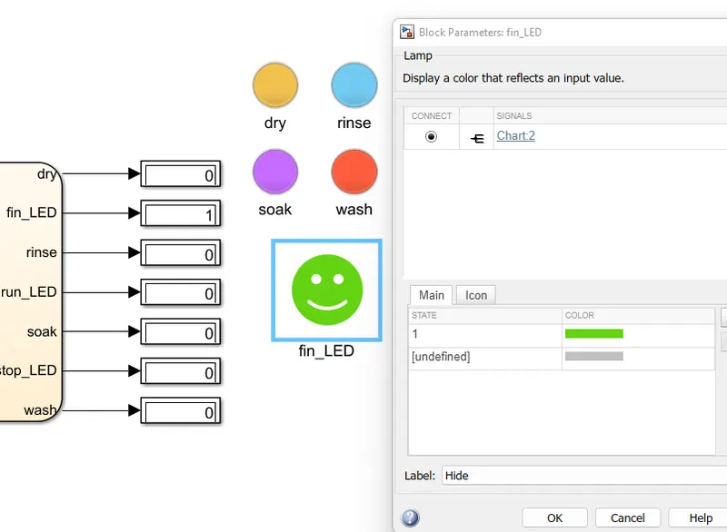
As can be seen if the operations are completed the finish LED is turned on by the value 1, and the same is represented by green color.
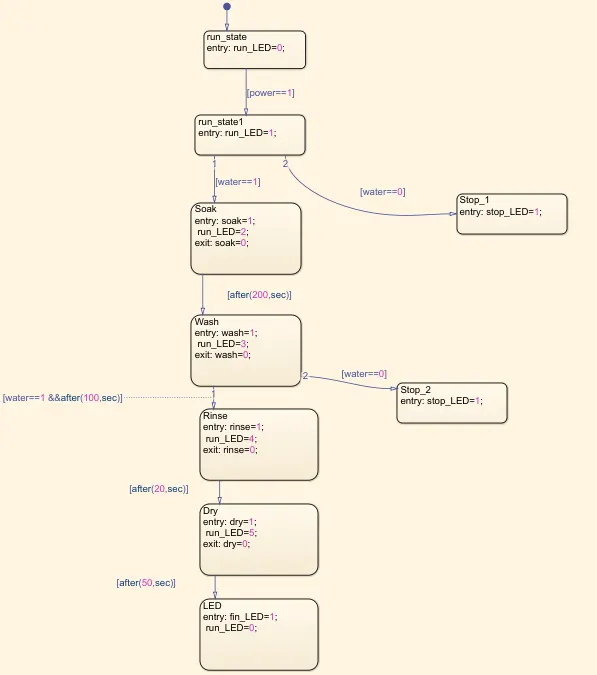
The chart for the washing machine opertaion can be seen below.
Step one.
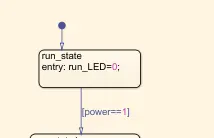
If the power is not present, run lamp will be off.
Step 2.
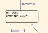
Once the power is given, the run LED Lamp turns 1.
Step 3.
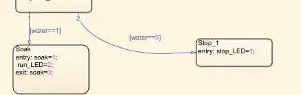
If the power is on, and if the water is available, then only the soaking stage will run or else it will not run.
To notify the soaking stage is ON the run lamp the value is given 2
if the power is available, but water is not available Stop LED Lamp will glow.
The same can be implemented by toggle switch in the main model.
Step 4.
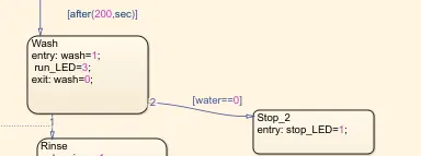
After a delay of 200 seconds from soaking stage, washing stage will start, which will be denoted by run LED 3.
At exit, Wash state will be 0.
Step 5.

The rinsing stage will start after a gap of 100 seconds and only if the water is available.
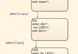
The rinsing state will continue for 20 seconds. And after that it will enter into drying state.
And exit from drying state with dry state notified by value =0.
Step 6.
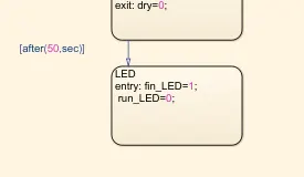
After exiting the dry state, the operations are finished and finished LED is turned one. That is, it is glowing as shown above.
Another option for Notifying the washing stages can be allotting only one lamp for all the operations but giving different color for different operations output. As shown below.
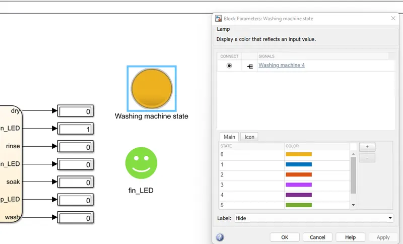
The color can be seen changing as the operation proceeds and the output ranges from zero to five and then back to zero.
Q2. Make a Simulink chart for the “Gear shift” logic as per below conditions:
Speed Range(kmph) Gear
0 to 15 1
16 to 25 2
26 to 40 3
41 to 60 4
Above 61 5
Give speed input while the simulation is running & display the gear number.
Ans:
The complete model of the gear shift logic is as follows.
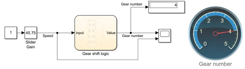
The input is given with a block using slider gain and having constant one as the base.
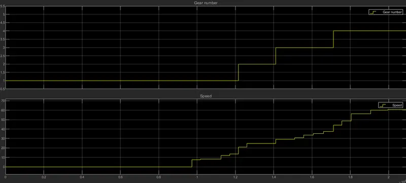
The output of the gear shift logic chart is plotted in the scope and the display is given in a display block and also in a dial gauge.
The chart of the gear shift logic is as follows.
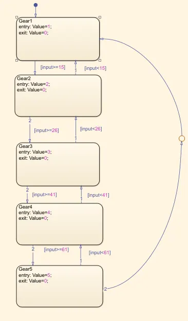
Initially it enters into gear one. Once the speed crosses 15, the gear two is selected/notified. Once the speed crosses 26, the gear three is notified and once the speed crosses 41, the gear four is selected and once the speed value is more than 61, gear five is selected and same gears are selected in reverse order based on the speed reduction.
The closed looping is achieved by using a junction block.
The simulation is Run for infinite time. The input to the slider gain is varied with time.
As we change the input to the slider gain Block. The output can be seen changing and the gears can be seen changing.