Week -2
Q1: Make a Simulink model of Doorbell using solenoid block with the following details:
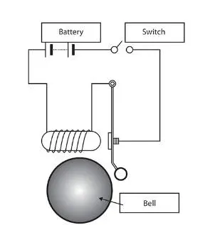
Create a situation where the switch is closed for 2 seconds and then released. Observe the physical movement of the plunger.
Ans 1:
SIMULINK MODEL IS AS FOLLOWS:
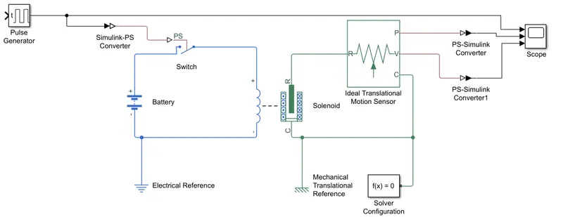
Blocks used:
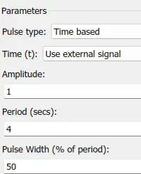
1. Pulse generator: To give the input of on & off time of 2 seconds as per probelm statement
2. Simulink to PS Convertor - To convert the simulink signal into Physical signal.
3. Switch - To turn on & off the the circuit as per pulse generators instructions
4. Battery- To supply power in circuit for solenoid operation
5. Solenoid- To ring the bell as per pulse given as input by pulse generator by moving the plunger when the circuit is closed by switch
6. Ideal translational motion sensor- To sense the translational motinn of solenoid
7. Mechanical translational reference - To give translational reference to solenoid plunger
8. Electrical reference - for grounding
9. Scope - To observe the results in plot
10. PS- simulink convertor- To convert the physical signal into simulink signal
Results:
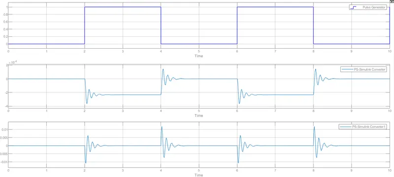
As can be seen as the pulse is given from 2-4 seconds the solenoid is displaced & the bell rings & as the pulse is cut off from 4-6 seconds, the solenoid is back to its oroginal position.
The velocity of operation is shown in bottom most graph.
Q2: Use a thermistor to sense the temperature of a heater & turn on or turn off the fan as per the below conditions:
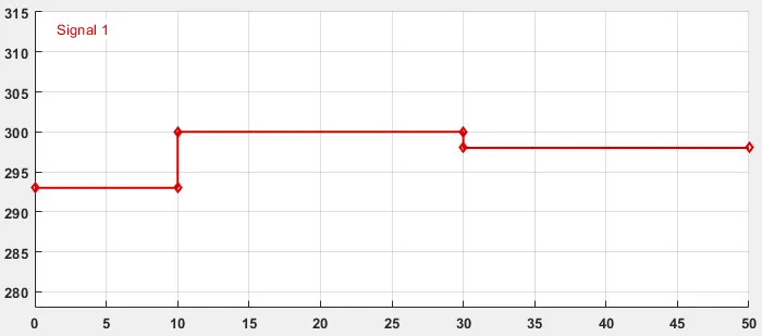
Temperature source: 20 °C from 0 to 10 seconds, 27 °C from 10 to 30 seconds, 23 °C from 30 to 50 seconds
Fan conditions: ON if the temperature above 25 °C, OFF otherwise
Ans 2:
Thermistor- Thermistor is a device used to measure the temperature. Output of thermistor is in terms of resistance.
SIMULINK MODEL IS AS FOLLOWS:
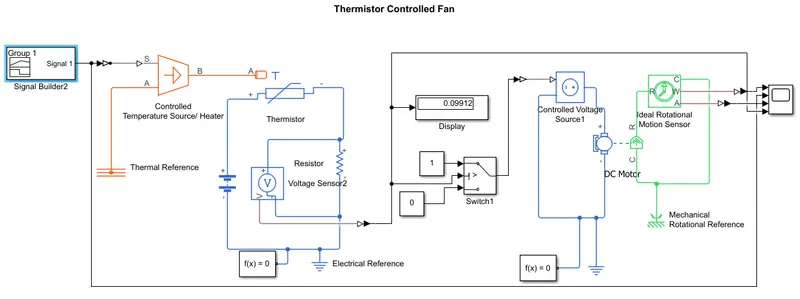
Blocks used:
1. Signal builder - To input the temperature in a fashion provided in the challenge statement.
2. Simulink to PS Convertor - To convert the simulink signal into Physical signal.
3. Controlled temperature source - works as heater to heat in fashion as stated in statement & give input to thermistor
4. Thermistor - To sense the temperature by changing its resistance
5. Resistor - connected in series in circuit
6. Voltaage sensor - Connected in parallel with resistor to sense the change in voltage according to temperature
7. Battery - To power the circuit with power supply
8. Electrical reference - for grounding
9. Solver- To solve the model
10. PS- simulink convertor- To convert the physical signal into simulink signal
11. Display - To see the voltage sensor sensor output at particular temperatures
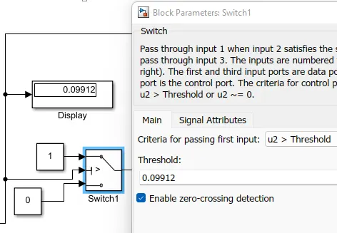
12. Switch- To turn on & off the DC motor fan as per the threshold
13. Controlled voltage source - To supply power supply to DC motor of fan
14. DC Motor - Working as a prime mover for fan
15. Thermal reference - To act a thermal grounding
16. Ideal rotational motion sensor - To measure the angular velocity & angular displacement
17. Scope - To observe the results in plot
18. Mechanical rotational reference - To give rotational reference to rotational sensor
The temperature is modeled in kelvin using Signal builder block as per problem statement.
The switch is given the threshold of 0.09912 which is the voltage measured across circuit when the temperature is 26 deg cel.
Results:
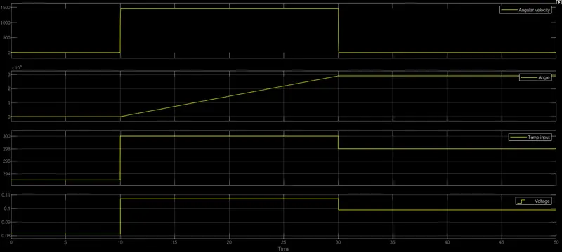
As can be seen, due to NTC nature of with the increase in temp, resistance drop & vice versa. Voltage follows the pattern of temperature.
Whenever the temp crosses 25 deg cel i.e., 298 kelvin the DC motor of fan is turned on as can be seen in angular velocity & angle graph and as the temp drops below 25 deg cel the dc motors fan is tirned off automatically.