Project
System level simulation of an all terrain vehicle
Aim: To study, simulate and analyze the BAJA all terrain vehicle model using Simulink and prepare technical report on the same.
Software used: Simulink.
Theory:
All terrain vehicle-
The term ATV stands for all terrain vehicle. It is also known as a quad or quadricycle type vehicle. ATV's have more than two wheels. The vehicle runs on low pressure tires. However, it has handlebars instead of a wheel for controlling the steering.
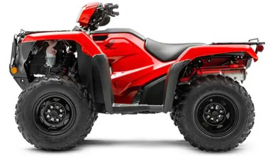
As the name indicates, manufacturers design and ATV's to handle a wider variety of terrain than regular vehicles. In some countries it is a street legal motor vehicle and licensed for use on public road. However, it is not street legal or roadworthy within some countries, states, territories and provinces.
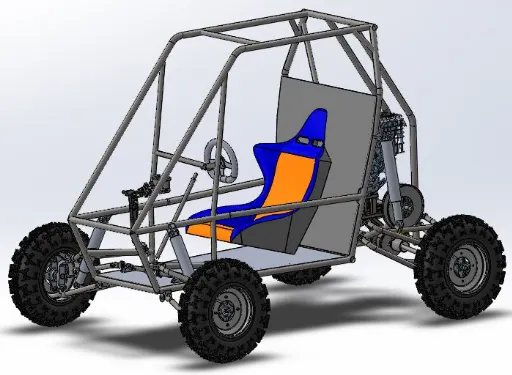
SAE BAJA ATV:
Baja SAE is an intercollegiate engineering design competition for undergraduate and graduate engineer students. The objective of the competition is to simulate real-world engineering design projects and their related challenges.
CVT (Continuously variable transmission)
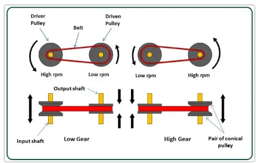
CVT or continuously variable transmission seamlessly changes through an unending range of effective gear ratios while you drive, whereas other kind of mechanical transmission offer a fixed number of gear ratios and have hard shifts between each. As explained by certified transmission repair. CVT transmission system are also known as single speed, shiftless and stepless transmissions.
One pulley in the CVT is connected to the engine and the other directs power to the wheels. The width of the pulleys changes based on the needed power as one gets larger, the other gets smaller. This allows the CVT to deliver strong and seamless acceleration.
Major components used in the ATV simulation using Simulink are:
- Generic engine block :
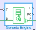
generate engine block represents the engine. It can be a petrol engine or a diesel engine. A physical signal ports output engine fuel consumption rate based on choice of fuel consumption model. Optional speed and red line controller prevent the engine stall and enable cruise control.
Block ports:
B=Rotational conserving port representing the engine block.
F=rotational conserving port representing the engine crankshaft.
T=Physical signal input port specifying the normalized engine throttle level.
P= physical signal output port reporting, the instantaneous engine power in Watts
FC= physical signal output port reporting the fuel consumption rate in KG per second.
- Variable ratio transmission block:
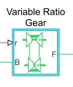
The variable ratio transmission block represents a gearbox that dynamically transfers motion and torque between the two connected drive shaft axes, base and follower.
R= defines the ratio of Input to output angular shaft velocities.
B & F= Base gear & follower gear-mechanical conserving rotational ports.
- Simple gear:
Represents a fixed ratio gear or gearbox. No inertia or compliance is molded in this block.

B & F= Base gear & follower gear- mechanical conserving rotational ports.
Gear Ratio=Radius or dia of Follower gear/ Radius or dia of base gear = Angular velocity of Follower gear/ Angular velocity of base gear
- Vehicle body:
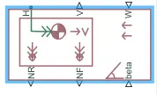
Represents a two-axle vehicle body in longitudinal motion. The block accounts for body mass, aerodynamic drag, road incline, and weight distribution between axles due to acceleration and road profile. The vehicle can have the same or a different number of wheels on each axle. Optionally include pitch and suspension dynamics or additional variable mass and inertia. The vehicle does not move vertically relative to the ground.
H =mechanical translational conserving port associated with the horizontal motion of the vehicle body.
V= Physical signal output port for Velocity
NR= Physical signal output port for Normal wheel force at rear
NF= Physical signal output port for Normal wheel force at front
W= physical signal input ports corresponding to headwind speed
Beta= physical signal input ports corresponding to road inclination angle
- Tire:
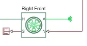
Tire block represents the longitudinal behavior of a highway tire characterized by the tire Magic Formula
A= mechanical rotational conserving port for the wheel axle
H= mechanical translational conserving port for the wheel hub
N= physical signal input port that applies the normal force acting on the tire
S= physical signal output port that reports the tire slip
- Double Shoe brake
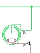
Represents a brake arranged as two pivoted rigid shoes symmetrically installed inside or outside a drum and operated by one actuator. The actuator force causes the shoes to exert a friction torque on a shaft connected to the drum.S-
S=conserving rotational terminal associated with the drum shaft
F= physical signal port representing the force input to the actuator
- Engine sensor block:
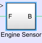
Comprises of ideal rotational sensor block.
Types of models given in project:
1. CVT model
2. CVT model dashboard
3. CVT model data
4. CVT model mapped
5. CVT model mapped dashboard
Model no 1. CVT model
- Main model & subsystem
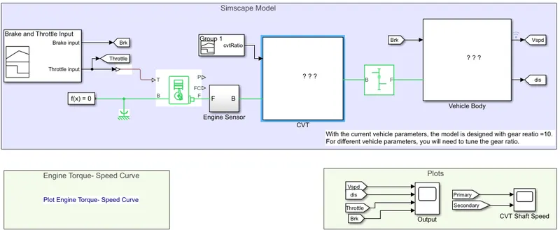
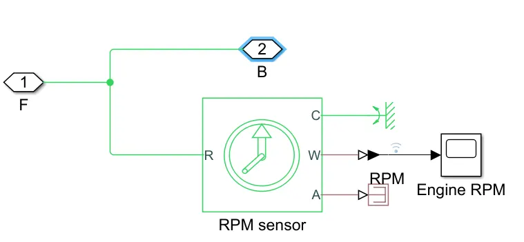
Engine sensor
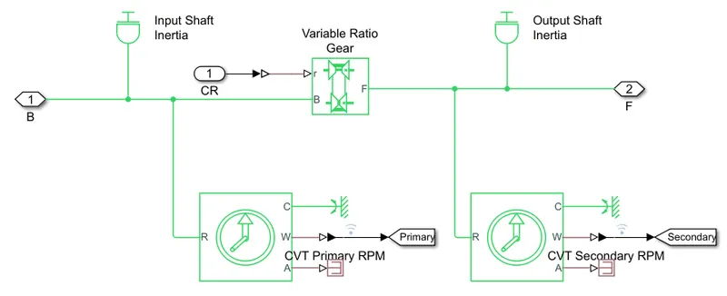
CVT transmission.
Vehicle body.
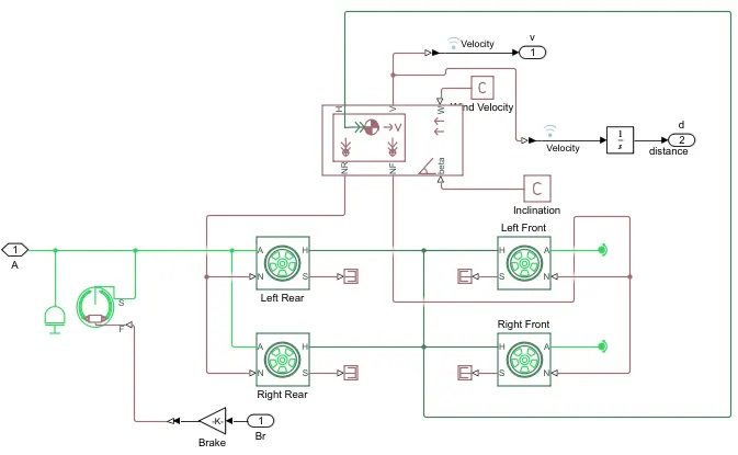
- Model description :
Input for the CVT mode:
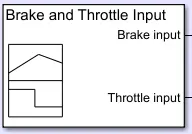
a) Input for the engine block is given in terms of throttle & brake through signal builder block as shown below,
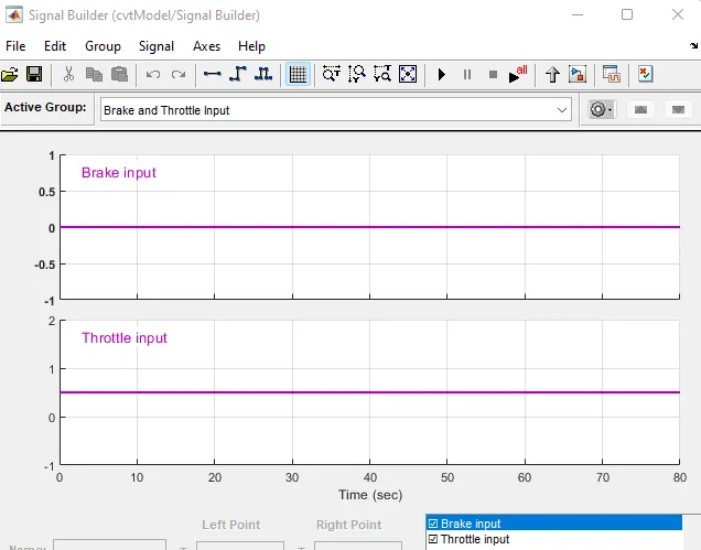
In the default model the brake input is zero. Only throttle input is present as seen below.
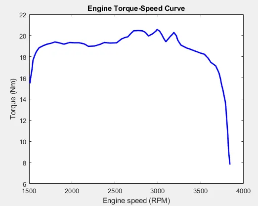
b) Input to the generic engine block is given by using a tabulated torque data, speed vector, torque vector in the Engine Torque tab in engine block & the values referred in matlab workspace.
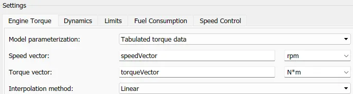
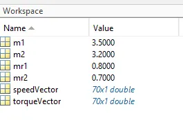
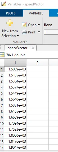
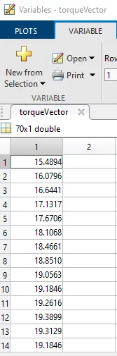
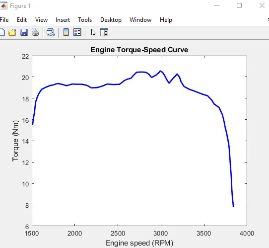
Initial Engine RPM is given as 1750 in input parameters of engine block.
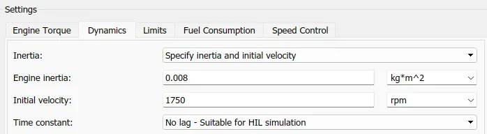
c) The output of engine which is crank shaft rotation in RPM is given as input to engine sensor having ideal rotational sensor.
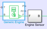
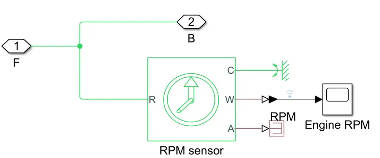
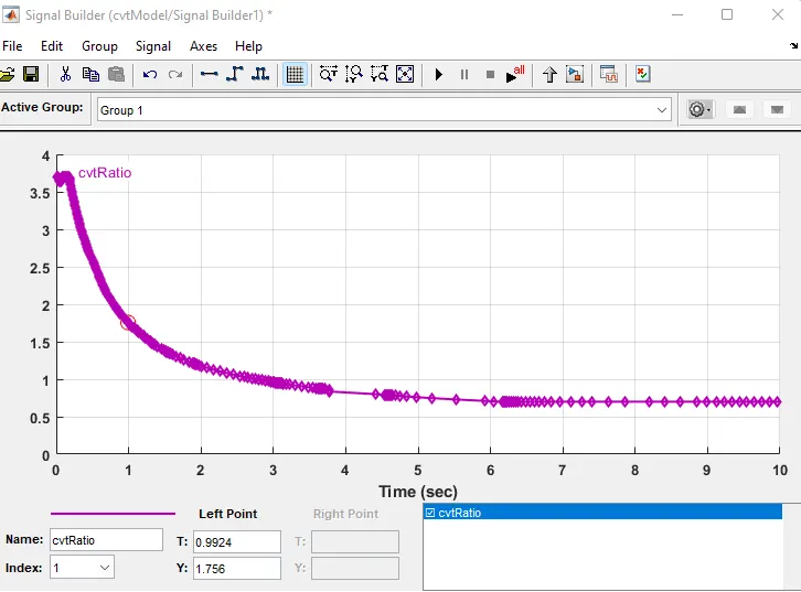
d) The output of sensor which is RPM is given as input to CVT transmission. The CVT ratio is fed to the transmission block using a signal builder block as shown below.
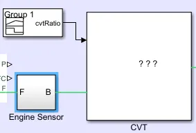
CVT Ratio which varies with time is represented using signal builder block as shown below:
Two rotational sensors log the RPM data of both primary & secondary pulleys.
The output of secondary pulley is given to a somple gear with fixed gaera ratio. The output of this block is input to tires.
Output plots:
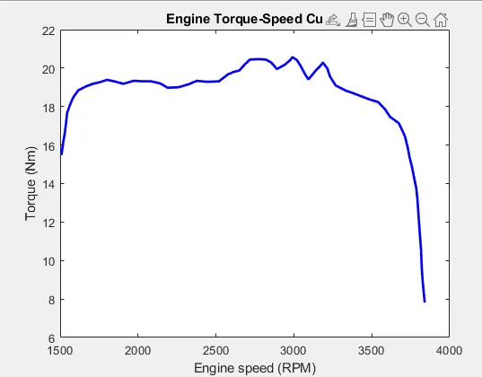
i) Engine tprque vs RPM
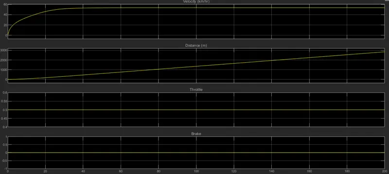
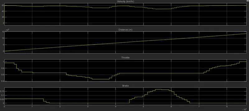
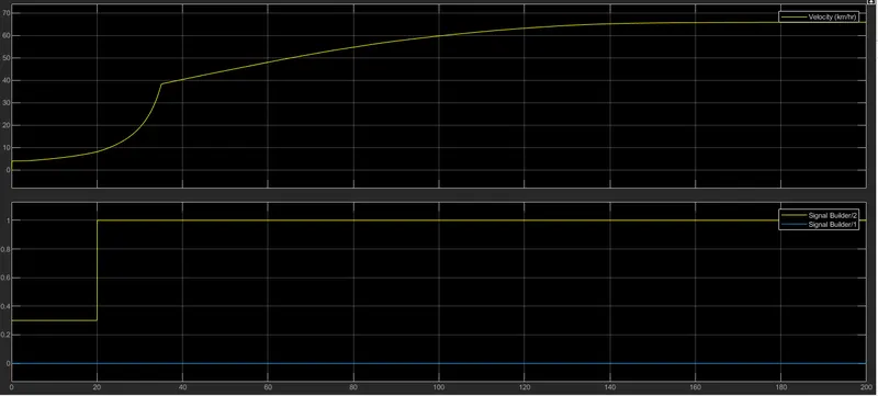
ii) Velocity, Distance, Throttle & brake vs Time
Observations:
The velocity becomes stagnant after some time because the gear ratio is constant after some tie & the throttle remains unchanged.
Distance keep incraesing as th evehicle does not stops.
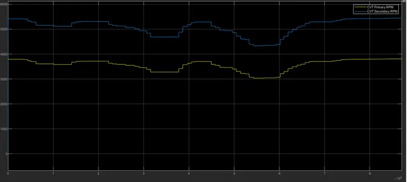
iii) CVT primary & secondary vs time
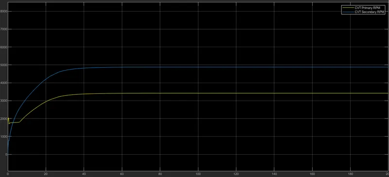
In the initial time of simulation the RPM, Gear ratio is Greater than 1 so RPM of secondary is less than primary and as the simulation is carried out for a longer time the secondary pulley RPM is more than primary which indicates the gear ratio in CVT is less than 1.
#2 Model: CVT model with dashboard
Main Model
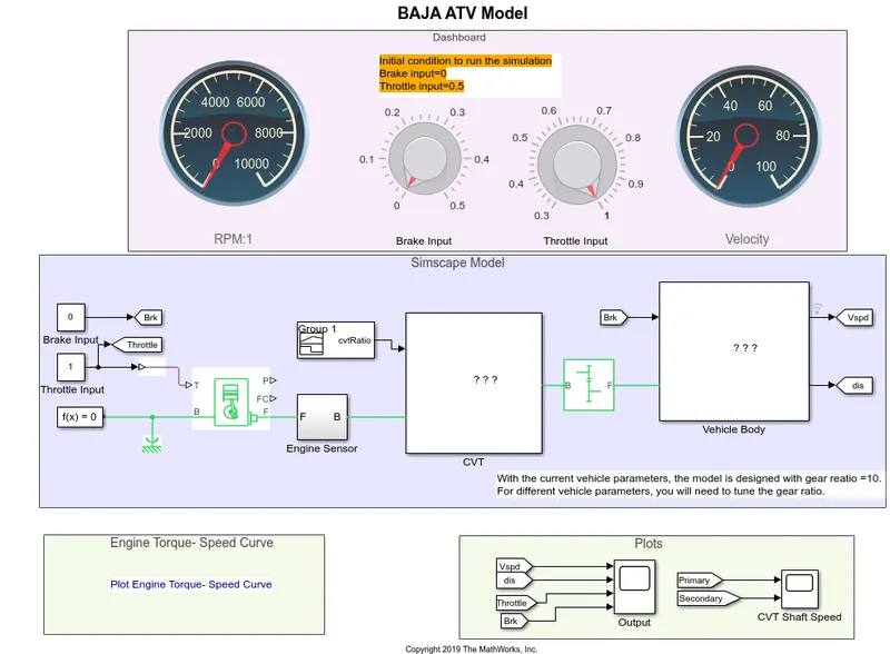
Subsystem:
The subsystem in this model is same as the basic CVT model (model 1)
Output plots:
Engine torque speed graph remains the same as given.
From the dashboard, by changing the throttle input & brake by knobs the velocity & distance changes as seen in th eresults.
At the same time the CVT ratio can also be seen changing.
Model 3: CVT model data
Main model:
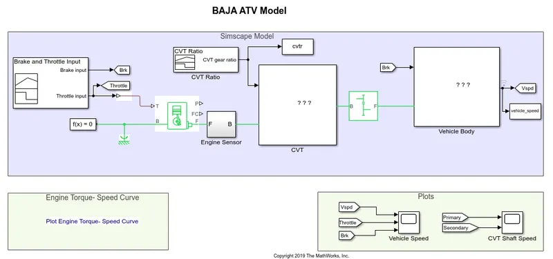
Subsystem: All the subsystems are same as model CVT model.
Flow Process
The flow process is also similar to CVT model, but there is an extra block called To Workspace which is connected to the CVT gear ratio. This block is used to send the CVT ratio to Matlab workspace and can be used for further analysis.
Output:
Velocity, Throttle, brake vs time
CVT ratio outputs
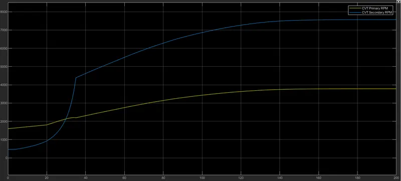
#Model 4: CVT with dashboard & Lookup table
Model
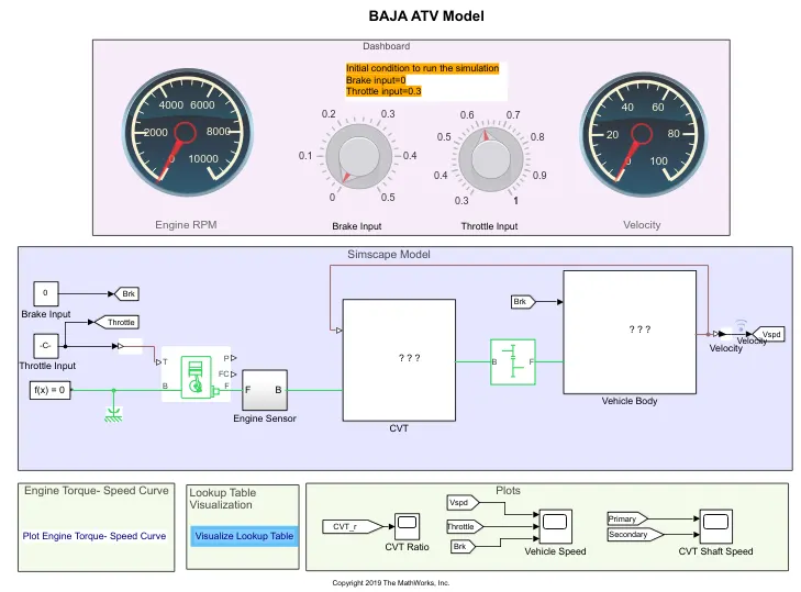
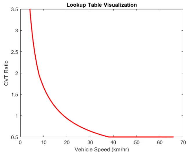
Subsystem: All the subsystems are same as model CVT model with dashboard but with a difference that velocity of the vehicle is taken as feed to the lookup table for establishing relation between CVT ratio and vehicle speed.
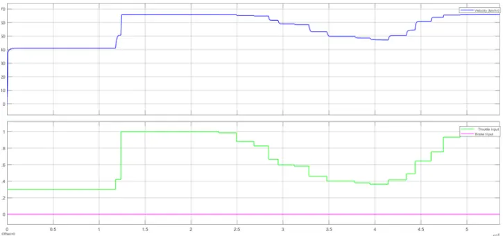
Outputs: Velocity, Throttle, brake vs time
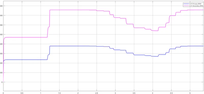
CVT ratios
Model 5: ATV with CVT with lookup table without the dashboard
MOdel:
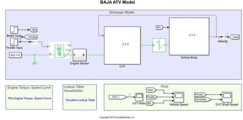
This model consists of lookup table, but the throttle & brake input is not given through the dials or constants but through the step block as shown below.
Throttle
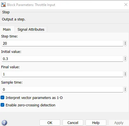
The initial value of throttle is 0.3. This is given for 20 time steps.
Brakes
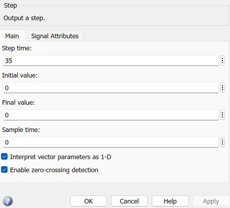
The brake value is zero.
Output plots:
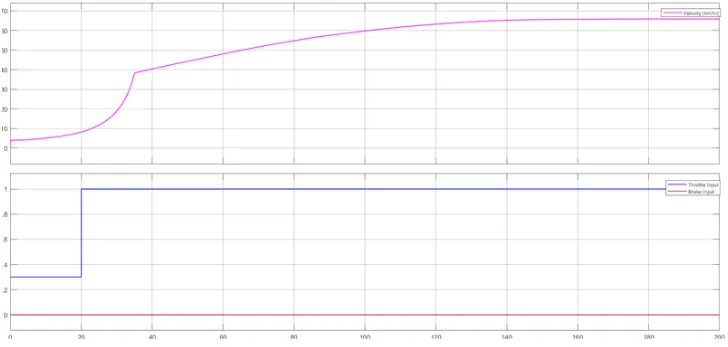
Velocity, Throttle, brake vs time
CVT ratios w.r.t time
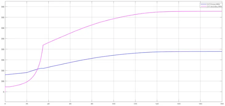
As can be seen with the change in input of throttle through step block th eoutput is changing in terms of velocity & CVT ratio.
END OF REPORT