Week - 4
1. CONTROL LOGIC OF WASHING MACHINE
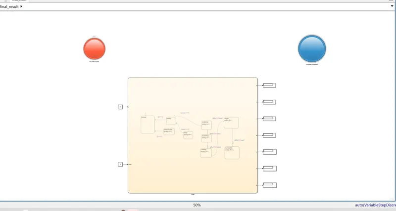
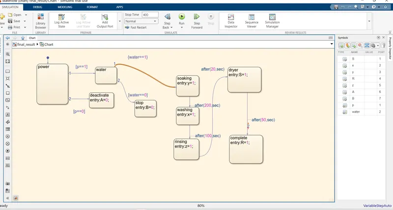
The 'Implemented control logic of a washing machine using state flow as shown in the above circuit. First of all in the question, they mainly mentioned about 'power' and 'water'. If both supply is not available, the machine should stop .
First of all , took chart and added the states. First state named as 'power'. It has 2 ports. 1st is supply ON condition and 2nd is supply OFF. To satisfy the condition, a 'deactivate' block is added from 2nd port as A=0 and for the first port is going to continue the process. So it goes to the state 'water'. It has also 2 ports. 2nd is unavailable of water supply. So made entry code as B=0. 1st port going to continue the process. So it going to the starting of washing process.
To continue the process, Soaking is the initial process. So made its entry code as y=1and it run for 200sec. Then next process is washing and entry code is x=1 and it run for 100sec. To continue the process, it's going to rinsing and dryer process and it's run for 20&50sec respectively and it's entry code as z=1and s=1.After 50sec, it's going to complete state,entry code as R=1
Here, two lamps needed to identify the following process.
1. If complete the washing, a lamp should be glow.
2. If water supply not available,another lamp should be glow.
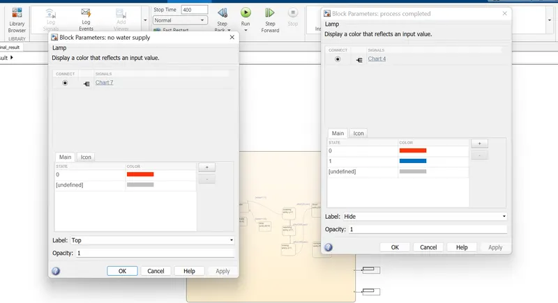
For the 2nd condition, a red light lamp is used and connect to display B.
For the first condition, a blue colour lamp is used and connect to display R.
Then select symbols pane to solve parameters and course either it is input or output. Otherwise the system shows unresolved parameter condition as error. So done as perfectly.
Now, comming out the inside chart.Now we can see 7 ports for output and 2 ports for input, which is already made at symbols pane window.R,S,X,Y,Z,A,B are 7 output ports and Power and water are input ports Now add each display for each 7 output.add 2 constants for input ports.lamp also connected for their displays. Now set sample time as 400 and hit run.
2. GEAR SHIFT LOGIC SIMULATION MODEL
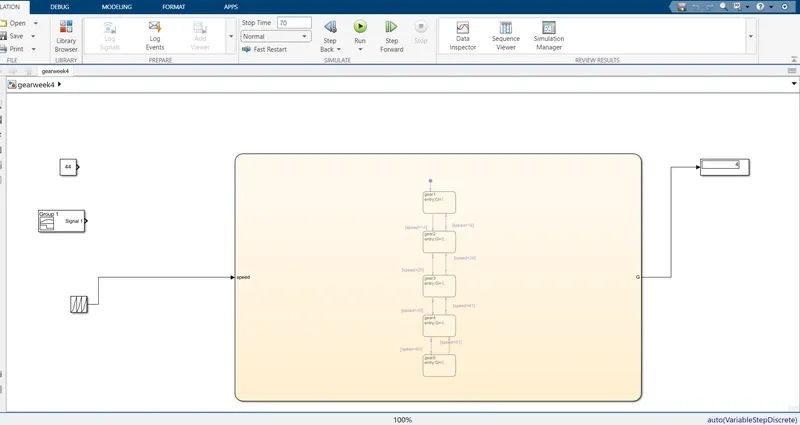
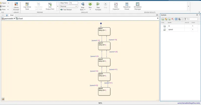
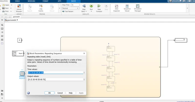 The 'gear shift model system' using stateflow chart is shown in the above figure. The condition is, it has 5 gears and it change with respect to the speed .
In order to create this model, use 'chart' from stateflow and take out 5 state and name it as gear 1,2,3,4,5 respectively entry code as G=1,2,3,4,5 respectively.Here 'G' act as output. Use arrows for up and down condition as input, in between each state's. Here, speed act as input. As per the condition of speed range 0-15 for 1st gear and 16+25 for the 2nd state,the arrows/input path placed inbetween gear 1&2 state and mentioned for outgoing arrow as 'speed is greater than 15' and incoming 'speed is lesser than 16, then only it will be return to 1st state from 2nd state.
Similarly, create input path for 2nd & 3rd state . Here 3rd gear range is 26-40.so outgoing path mentioned as speed is greater than 25 and outgoing as speed is lesser than 26.
The gear 4 range is 41-60.so between gear 3&4, outgoing path is ' speed is greater than 40 and incoming as 'speed is lesser than 41.
Gear 5th range is above 61.So gear 4& 5 state, outgoing path as 'speed is greater than 60' and incoming as'speed is lesser than 61'.
Now use symbols pane from tool bar and make its input and output. Here, G is output and speed is input.
Now coming out from the chart and add display and a constant as output and input blocks.
Now choose a value for constant and Run the model and get the proper gear number from the output display, which is w.r.t the input value of the constant block.