Week - 4
TASK 1 :
To implement the logic control of a washing machine using state flow
Objective:
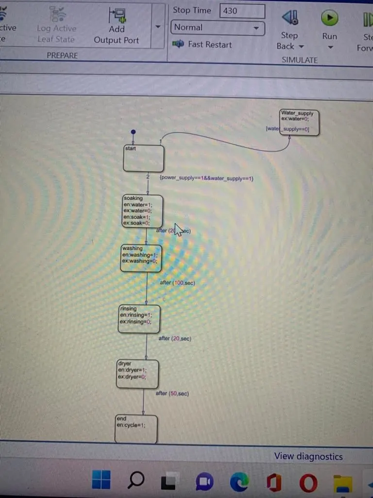
1.If the power supply is available then the system gets activated.
2.If the water supply is not available then stop the process and indicate through on the LED.
3.Soaking time should be 200 sec followed by the washing time of 100 sec.
4.Rinsing happens for 20 sec followed by dryer of 50sec.
MODEL:
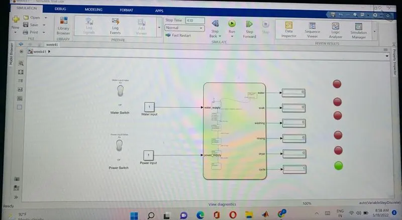
The block diagram representation of washing machine
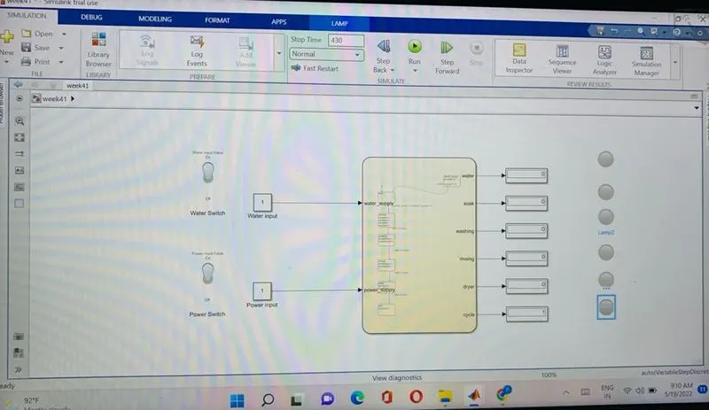
parameters
1. Value 1 means there is input.
2.Value 0 means there is no input.
The flow chart of the washing machine
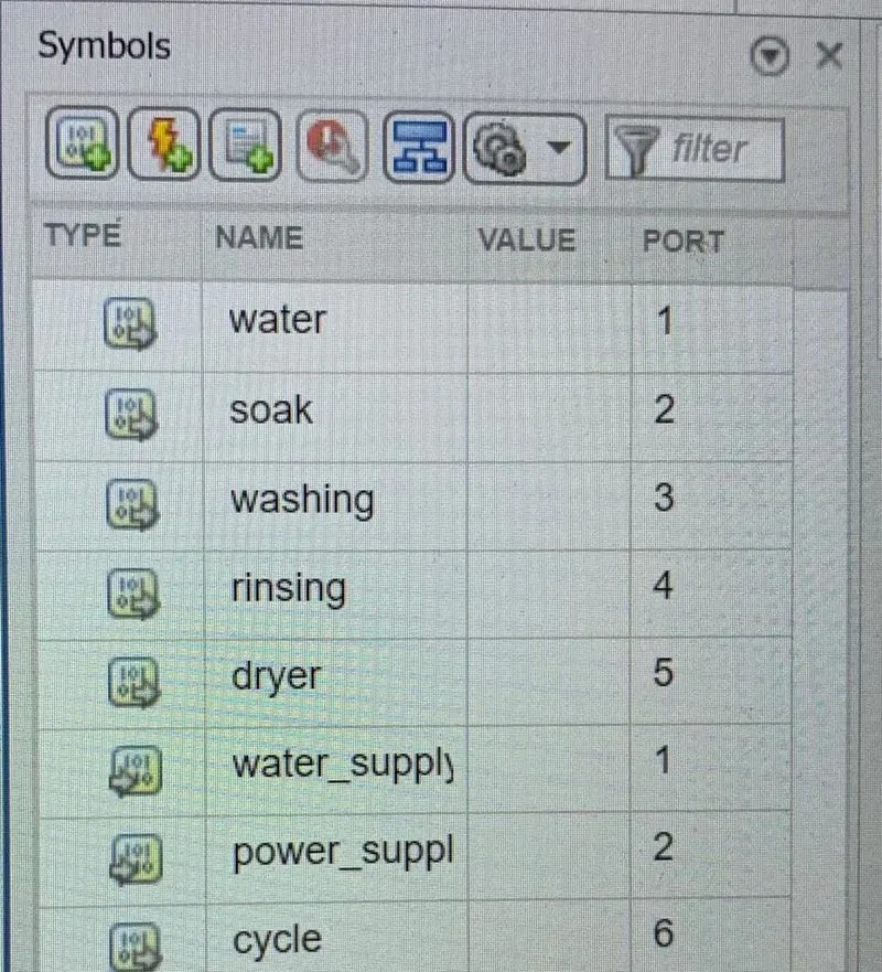
The input and output parameters are:
The simulation time is taken has 430 sec so that it can cover the whole cycle and sufficient time to store and solve the problems.
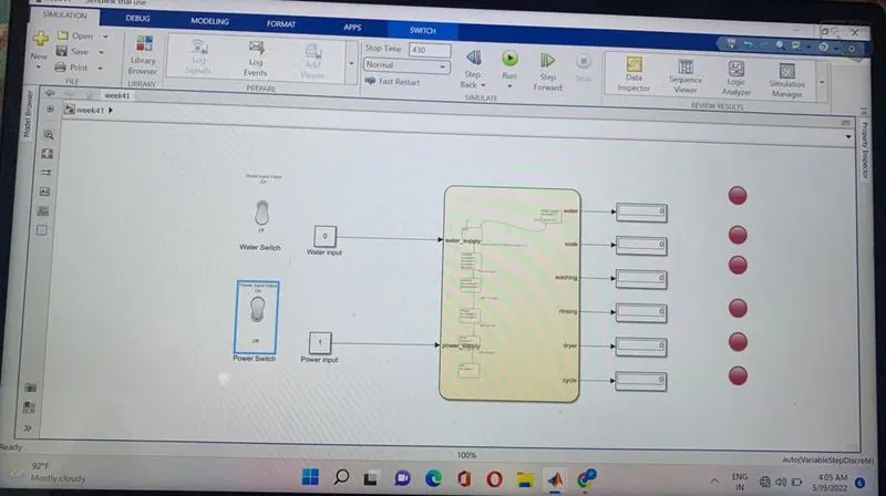
OUTPUT : If the water supply is off
In this case we are not providing the water to washing machine.
OUTPUT: If the water switch is on
In this case the water is supplied to washing machine.
CONCLUSION:
From the above process we can say that the simulation of washing machine is done using state flow.
TASK 2:
Aim:
Make simulink logic for gear shift logic has per the given conditions
Speed Range Gear
0 to 15 1
16 to 25 2
26 to 40 3
41 to 61 4
Above 61 5
Give speed input while simulation is running and dispaly the gear number
block diagram:
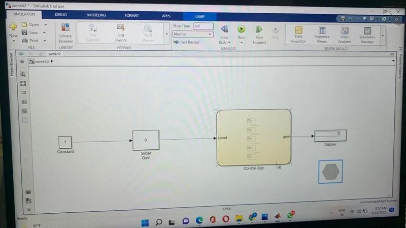
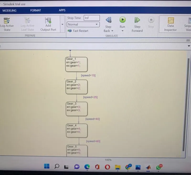
chart diagram
The output is given when we give input through slider gain
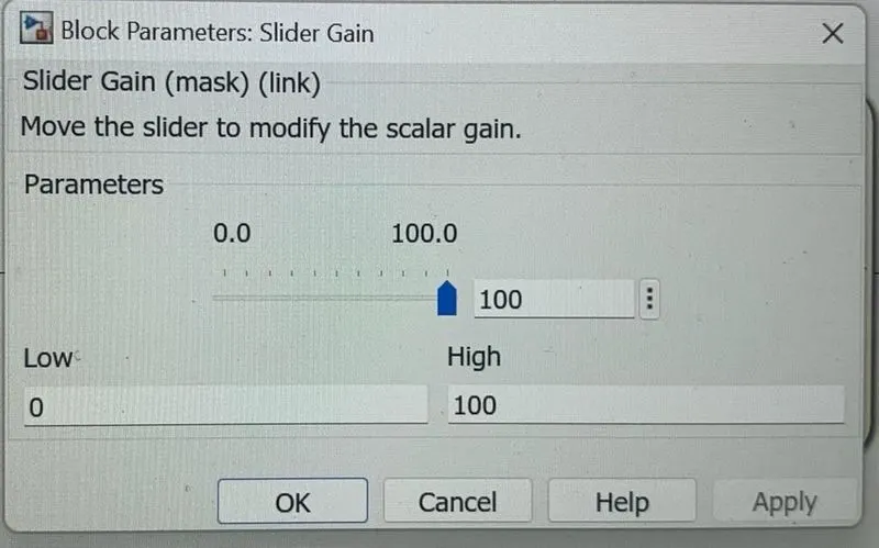
The range of speed is from 0 to 100 kmph slider gain acts as speed input
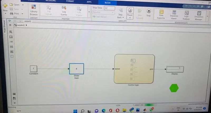
gear 1
speed range:0 kmph to 15kmph
color : green
input speed : 8 kmph
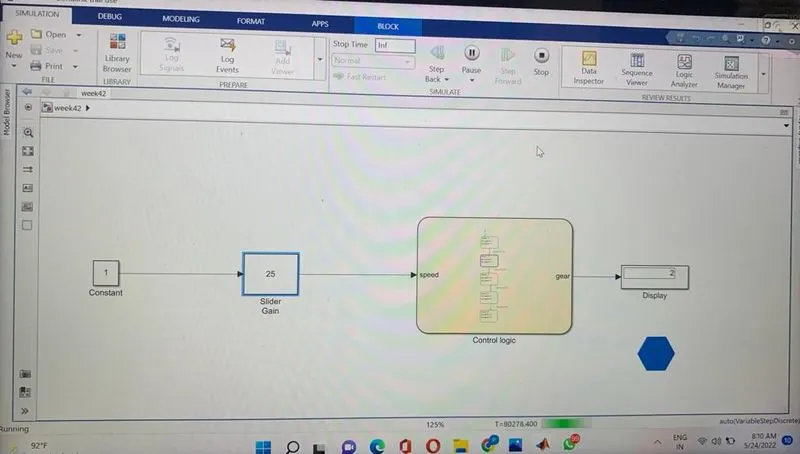
gear 2:
speed range:16 kmph to 25kmph
color :blue
input speed : 25 kmph
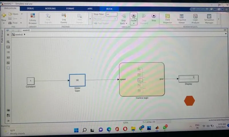
 gear 3
speed range:26 kmph to 40 kmph
color : maroon
input speed :38 kmph
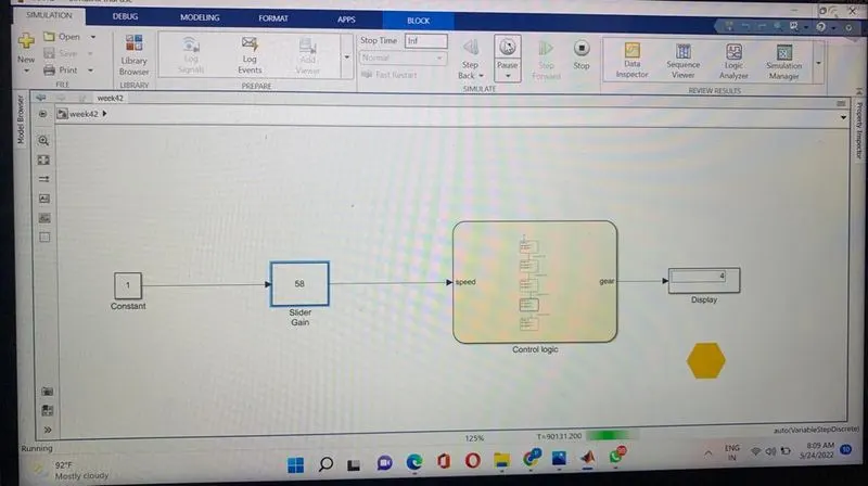
gear 4
speed range:41kmph to 60kmph
color :yellow
input speed : 58 kmph
gear 5
speed range :61 kmph to 100kmph
color :violet
input speed : 94kmph
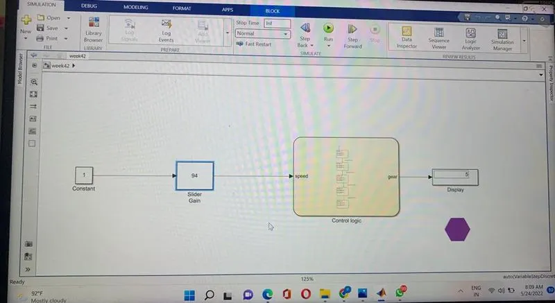
1.From the above figures we can observe that in each figure when the speed in the slider gain changes the color of the lamp changes with respect to the gear in the dispaly box.
2.This is because we have given a specific range of speed for each gear the control logic takes the input and reads the input starts from the gear 1 if the speed range is in gear 1 then gear 1 executes in display box if not the range in gear 1 it passes to the next gear goes untill end.
conclusion:
Created a state flow for gear shift using simulink and the results are satisfactory.