Week - 4
Task-1:
Aim:
Implement control logic of a “washing machine” using Stateflow as per given sequence:
- If the power supply is available, the system gets activated
- If the Water supply is not available, stop the process & indicate through LED
- Soaking time should be 200s followed by Washing time of 100s.
- Then rinsing happens for next 20s & dryer runs for 50s
After all the processes have completed turn on the finished LED.
Introduction:
Automatic washing machines work on a very simple principle; they agitate clothes rapidly in soapy water until they’re clean and then clean water replaces the soapy water until the clothes are rinsed completely. This process removed all the stains and dirt from the clothes, making them clean.
In this simulation, four operations of automatic washing machine i.e. Soaking, Washing, Rinsing and Drying will be done if power and water supply is available. Controlling of automatic washing machine will be done using Stateflow.
Theory:
Lamp colour output conditions:
|
Lamp name |
Colour |
|||||
|
Green |
Yellow |
Red |
||||
|
Value |
State |
Value |
State |
Value |
State |
|
|
Power |
1 |
Entry |
- |
- |
0 |
Exit |
|
Water |
1 |
Entry |
- |
- |
0 |
Exit |
|
Soak |
2 |
Exit |
1 |
Entry |
- |
- |
|
Wash |
2 |
Exit |
1 |
Entry |
- |
- |
|
Rinse |
2 |
Exit |
1 |
Entry |
- |
- |
|
Dry |
2 |
Exit |
1 |
Entry |
- |
- |
|
Cycle complete |
1 |
Entry |
- |
- |
- |
- |
|
Stop |
- |
- |
- |
- |
1 |
Entry |
Table 1: Lamp colour output conditions
In this simulation, automatic machine behaviour will be observed for below 3 conditions:
- Condition 1: Power Supply=1, Water Supply=1;
- Condition 2: Power Supply=1, Water Supply=0;
- Condition 3: Power Supply=1, Water Supply=0 after 300 secs;
1. Condition 1 - P=1 & W=1:
Refer to below simulation model pictures:
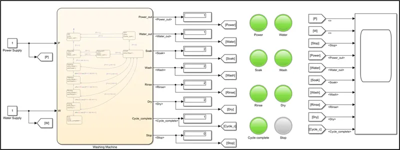
Fig 1: Simulink model picture
Observation from figure 1:
- Power, Water, Soak, Wash, Rinse, Dry and Cycle complete lamps are green as per Table-1 condition.
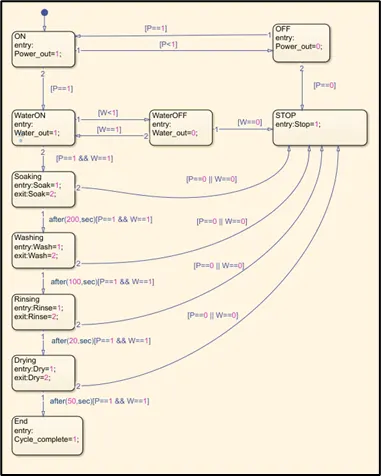
Fig 2: Washing Machine Stateflow logic picture
Refer below simulation graph:
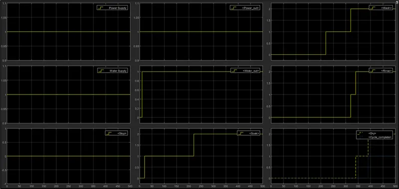
Observation from above result:
- In 0 to 20 secs, Power input and water input logic conditions are checked.
- In 20 to 220 secs, Soak cycle is running.
- In 220 to 320 secs, Wash cycle is running.
- In 320 to 340 secs, Rinse cycle is running.
- In 340 to 390 secs, Dry cycle is running.
- At 390 secs, cycle is complete.
2. Condition 2 - P=1 & W=0:
Refer to below simulation model pictures:
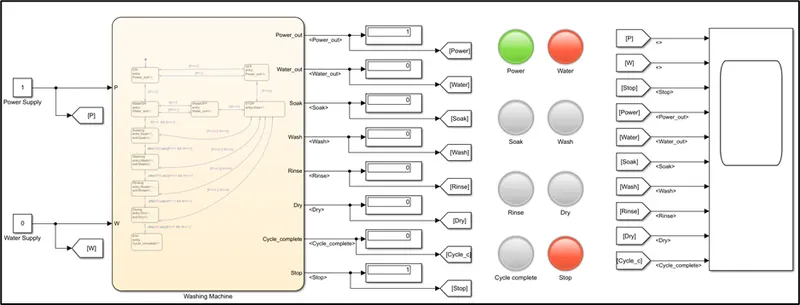
Fig 3: Simulink model picture
Observation from figure 3:
- Power lamp is green as per Table-1 condition.
- Water and Stop lamps are red as per Table-1 condition
3. Condition 3 - P=1 & W=0 after 300 secs:
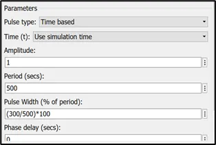
Fig 4: Water supply input
Refer to below simulation model pictures:
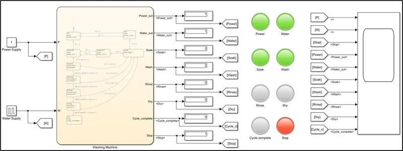
Fig 5: Simulink model picture
Observation from figure 5:
- Power, Water, Soak, Wash lamps are green as per Table-1 condition.
- Rinse, Dry, cycle complete lamps are not ON because Water supply is OFF after 300 secs so wash operation gets stopped and Stop light turn on red.
Refer below simulation graph:
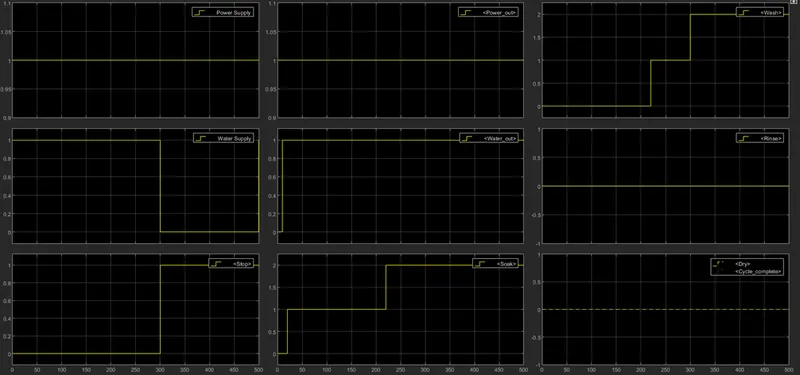
Observation from above result:
- In 0 to 20 secs, Power input and water input logic conditions are checked.
- In 20 to 220 secs, Soak cycle is running.
- In 220 to 300 secs, Wash cycle is running and after 300 secs wash cycle is interrupted as no water supply, so further operations stop.
Summary:
With the help of Stateflow, automatic washing machine logic conditions are satisfied as per objective.
Task-2:
Aim:
Make a Simulink chart for the “Gear shift” logic as per below conditions:
|
Speed Range(kmph) |
Gear |
|
0 to 15 |
1 |
|
16 to 25 |
2 |
|
26 to 40 |
3 |
|
41 to 60 |
4 |
|
Above 61 |
5 |
Give speed input while the simulation is running & display the gear number.
Introduction:
In this simulation, automobile gear will be automatically changed according to speed input.
Theory:
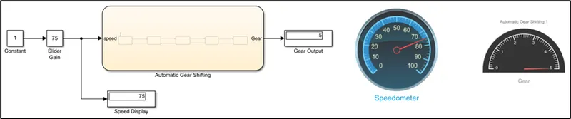
Refer to below simulation model picture:
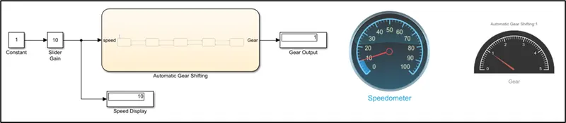
Fig 1: Simulink model picture

Fig 2: Automatic gear shifting Stateflow logic picture
Slider gain block:
It is used to change the speed input during simulation run.
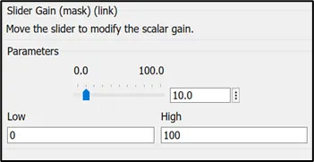
Fig 3: Slider gain block picture
Speedometer dashboard:
Display the speed output.
Gear dashboard:
To display Gear number.
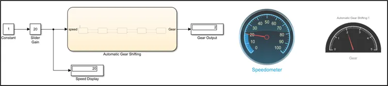
1. Condition 2 – Speed = 20kmph:
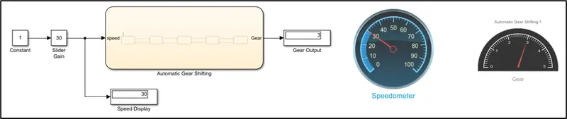
2. Condition 3 – Speed = 30kmph:
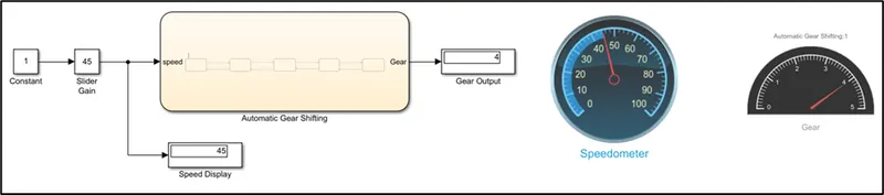
3. Condition 1 – Speed = 45kmph:
4. Condition 1 – Speed = 75kmph:
Summary:
With the help of Stateflow, automatic gear shifting logic conditions are satisfied as per objective.