Week -2
Part-1:
Aim:
Make a Simulink model of Doorbell using solenoid block with the following details:
In the above arrangement, when the switch is closed the electromagnet receives electrical power from the battery and pulls the metal arm to hit the bell producing sound.
Create a situation where the switch is closed for 2 seconds and then released. Observe the physical movement of the plunger. Assume remaining parameters.
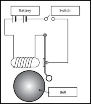
Fig 1: Doorbell model example
Introduction:
A solenoid is a type of electromagnet formed by a helical coil of wire whose length is substantially greater than its diameter, which generates a controlled magnetic field. The coil can produce a uniform magnetic field in a volume of space when an electric current is passed through it. The plunger is attracted to the stop through the concentration of the magnetic field providing the mechanical force to do work. A Spring take back the plunger to its initial position when electric current flow is cut off.
- The coil is made of many turns of tightly wound copper wire. When an electrical current flows through this wire, a strong magnetic field/flux is created.
- The housing, usually made of iron or steel, surrounds the coil concentrating the magnetic field generated by the coil.
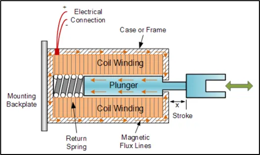
Fig: 2 Solenoid Example
In this simulation, a model will be made in which, pushing the bell swich will close the switch and connects the electromagnetic coil to the battery. The activated electromagnet then attracts the plunger, which hits the bell and makes a sound. Doorbell switch is closed for 2 seconds only.
Theory:
Refer to below simulation model picture:
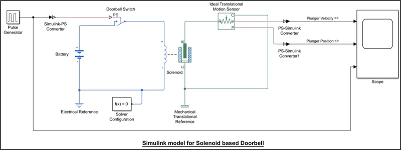
In this model, simulation time is 8 secs:
- A battery, Switch and Solenoid block is used to create Solenoid electric circuit.
- Doorbell switch is controlled by a Pulse generator which ON the Switch for 2 secs only. Refer fig. 3 for parameters inputs of Pulse generator block.
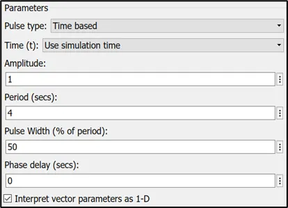
Fig 3: Parameters inputs for Pulse Generator Block
- When Swich is ON, a current pass to the electromagnetic coils of the solenoid and solenoid gets magnetised which attracts the iron plunger. This attraction causes the linear movement of the plunger.
- An Ideal translational motion sensor block is used to capture the plunger movement which gives outputs in the form of plunder velocity and position.
- Outputs of the Ideal translational motion sensor and pulse generator block are connected to a scope to observe the waveforms.
- An electrical reference and a mechanical translational reference are provided to the electrical circuit and mechanical circuit respectively.
- Solver configuration is connected to the circuit so that is specifies solver parameters to the model.
Refer below graph for plunger velocity, plunger position and pulse generator output:
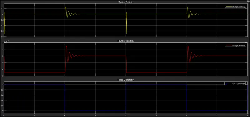
Observation from above result:
- In 0-2 secs period, pulse generator output is 1, Plunger position is move from 0 to -5X10⁻³ m (approximately).
- After 2 secs, pulse generator output is 0, Plunger position comes from -5X10⁻³ m to 0. That means after 2 secs, plunger returns to its original position.
Summary:
When switch is ON, solenoid is magnetised which attracts the plunger. The movement of plunger is linear.
Part-2:
Aim:
Use a thermistor to sense the temperature of a heater & turn on or turn off the fan as per the below conditions:
Temperature source: 20 °C from 0 to 10 seconds, 27 °C from 10 to 30 seconds, 23 °C from 30 to 50 seconds
Fan conditions: ON if the temperature above 25 °C, OFF otherwise
Introduction:
The thermistor is basically a two-terminal solid state thermally sensitive transducer constructed using sensitive semiconductor-based metal oxides with metallised or sintered connecting leads formed into a ceramic disc or bead.
This allows the thermistor to change its resistive value in proportion to small changes in ambient temperature. In other words, as its temperature changes, so too does its resistance and as such its name, “Thermistor” is a combination of the words THERM-ally sensitive res-ISTOR.
PTC (Positive Temperature Coefficient) thermistors resistance increases with temperature rising. NTC (Negative Temperature Coefficient) thermistors resistance decreases with temperature rising.

Fig: 1 Thermistor picture
In this simulation, a model is made in which, a signal builder is used to create the temperature output of 20 °C from 0 to 10 seconds, 27 °C from 10 to 30 seconds, 23 °C from 30 to 50 seconds. The output of signal builder is connected to the controlled temperature source. Thermistor is connected to the temperature source and its resistance changes as temperature changes. Thermistor provides output in form of voltage. A controlled switch is used and its condition is given as when voltage > 6.123 (equivalent to 25°C temperature) then only current flows to the motor circuit and motor starts running. Output of motor is taken through rotational sensor.
Theory:
Refer to below simulation model pictures:
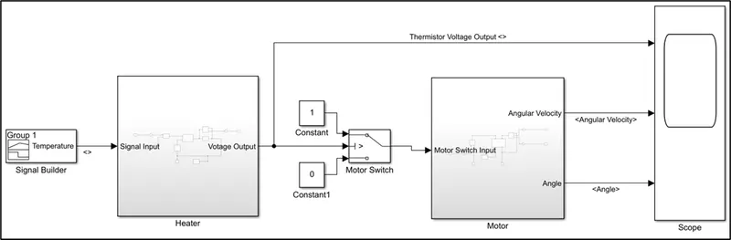
Fig 2: Main System model
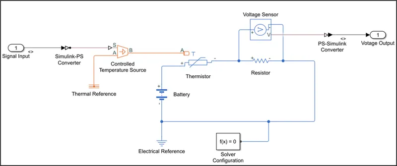
Fig 3: Heater Sub-system model
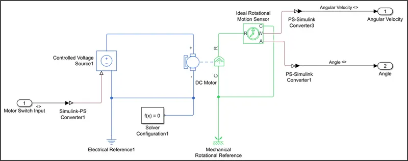
Fig 4: Motor Sub-system model
In this model, simulation time is 50 secs:
- At first, signal builder block is used to provide Temperature input to the Temperature source in kelvin. Refer fig 5 for Signal builder waveform information.
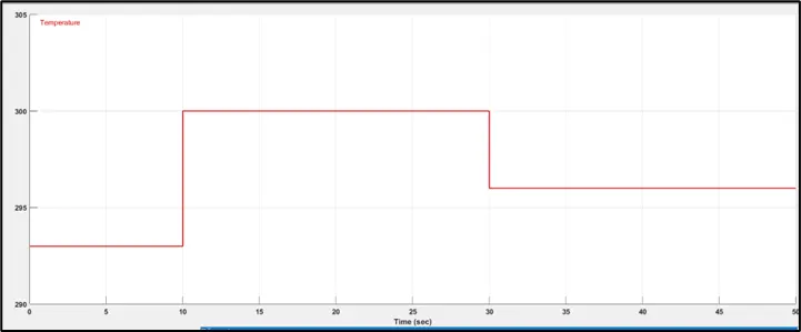
Fig 5: Signal builder input
- Signal input is given to the Heater sub-system.
- In Heater sub-system,
- Signal input is given to controlled temperature source block. A thermal reference is attached to the temperature source block and its output is connected to the input of Thermistor block.
- Thermistor block is connected to the battery source. A resistor is connected in series to the Thermistor.
- A Voltage sensor block is connected in parallel to the resistor to measure the voltage drop in Thermistor due to the change in Temperature.
- Thermistor voltage output is given to the Motor switch in main system.
- A controlled fan switch block is used which get ON only when Voltage output > 6.123 V (6.123 voltage output is generated from Thermistor at 25°C temperature). Refer fig 6 for motor switch condition parameter.
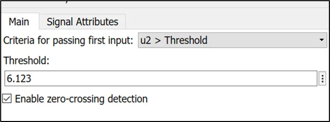
Fig 6: Motor switch condition parameter
- Output of motor switch is given to the Motor sub-system.
- In motor sub-system:
- Output of switch is given to the controlled voltage source.
- A DC Motor block is connected to the controlled voltage source.
- When switch is ON, Motor runs and it produces the rotational mechanical movement.
- Ideal motor rotational sensor is used to sense the angular velocity and angle of Motor.
- Outputs of Ideal motor rotational sensors are taken out in the main system.
- Outputs of Transistor voltage, motor angular velocity and motor angle are connected to the scope to measure the waveforms of all outputs.
- An electrical reference and a mechanical rotational reference are provided to the electrical circuit and mechanical circuit respectively.
- Solver configurations are connected to the circuit so that is specifies solver parameters to the model.
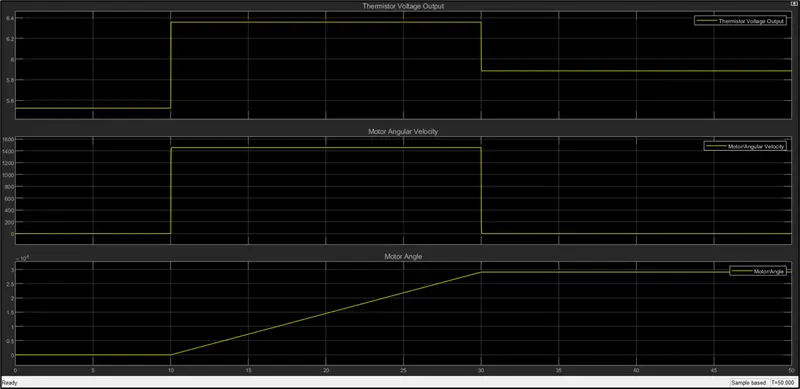
Refer below graph for Transistor voltage, motor angular velocity and motor angle:
Observation from above result:
- Motor is ON between 10 to 30 secs period only as Temperature sense by Transistor in this period is >25°C.
Summary:
- Motor gets ON only when temperature is >25°C.