Week-4 Challenge on control logic of Washing Machine and Gear Mechanism using Stateflow
Week 4 Challenge
Part 1
Aim: Implement control logic of a “Washing Machine” using Stateflow.
Objectives: Implement control logic of a “Washing Machine” using Stateflow as per given sequence:
- If the power supply is available, the system gets activated.
- If the Water supply is not available, stop the process & indicate through LED.
- Soaking time should be 200s followed by Washing time of 100s.
- Then rinsing happens for next 20s & dryer runs for 50s.
Understanding the model
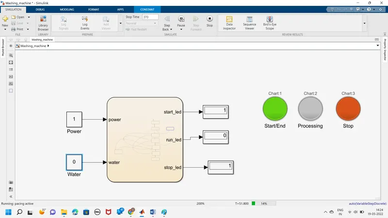
In our given problem, we have to model a washing machine and simulate its running for the given set of conditions. Let’s understand how the model has been built.
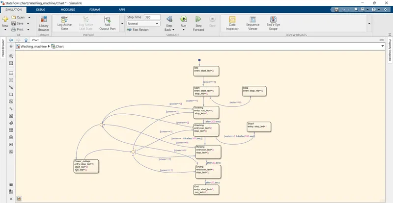
1) We’ll be working on Stateflow in this problem, hence we use the ‘chart’ block. In the ‘chart’ block, we first create the idle state wherein the machine is in the idle state before switching it on.
2) Next we create the start state, wherein we start the machine. The condition here is that the power supply should be on to start the machine; else the stop led will glow.
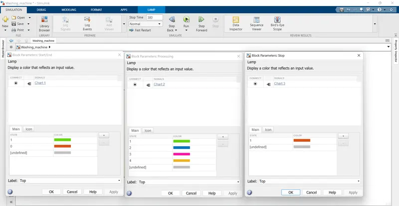
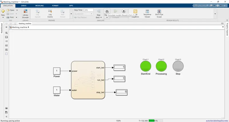
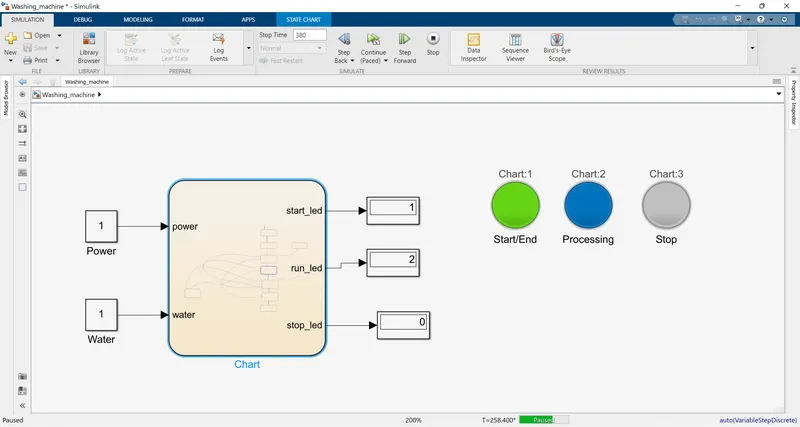
3) Our next state shall be the soaking state. The precursor for this state though is that water must be available for it to run and it has been mentioned in the state transition condition. If water supply is available then a green led will glow in the run led and the operation will run for 200 seconds. If not, the stop led will glow and the operation won’t run.
4) Next up is the washing state wherein the operation will run for 100 seconds. The run led will glow with a blue light while the operation is in progress.
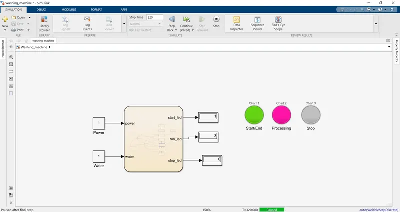
5) On completion of the washing state after 100 seconds, the rinsing operation will take place. Again here the precursor is that there should be fresh available for rinsing. If that is available, the run led will glow with a pink light and the operation will run for 20 seconds. If fresh water is not available, the stop led will glow with a red light and the operation won’t be executed.
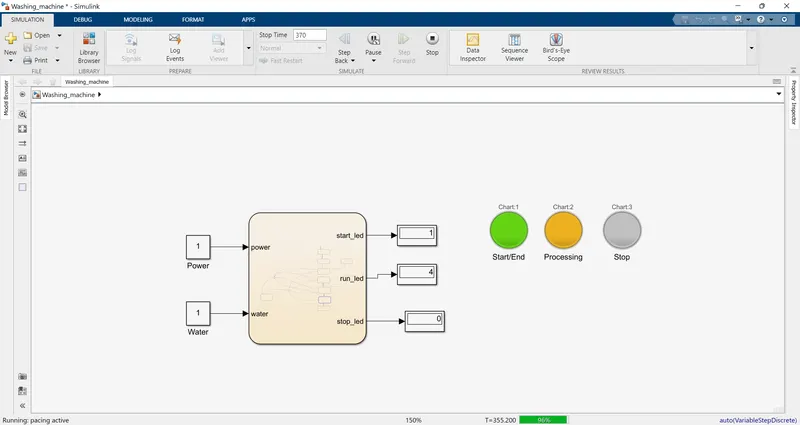
6) The final process is that of drying. While running this operation, the run led will display an orange light and the operation will run for 50 seconds.
7) On completing these series of operations, the start led will display a red light indicating the end of the process.
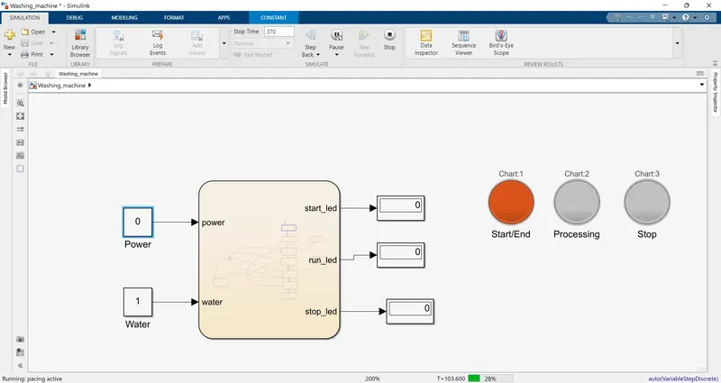
If at any stage there is a power outage, the stop led will glow indicating the same and once the power is back again, the process will resume its operation from where it had halted. The input to this chart has been given in the form of two constants: one for power and the other for water. The on and off states are indicated by 1 & 0 respectively. The start, run and stop led outputs are connected to 3 displays and each display is connected to a lamp to indicate the running status.
The Model
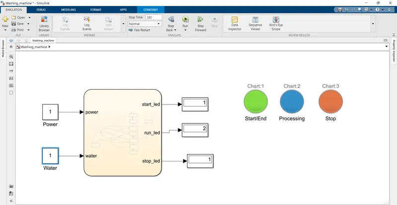
https://drive.google.com/file/d/15wZqacdXL9fw_AbEY2YVpTx6to9EYvV2/view?usp=sharing
Running States
1) Soaking
2) Washing
3) Rinsing
4) Drying
5)Power outage or water unavailability inputs
Part 2
Aim: Implementing control logic of a “Gear mechanism” using Stateflow.
Objectives: Make a Simulink chart for the “Gear shift” logic as per below conditions:
Speed Range (kmph) Gear
0 to 15 1
16 to 25 2
26 to 40 3
41 to 60 4
Above 61 5
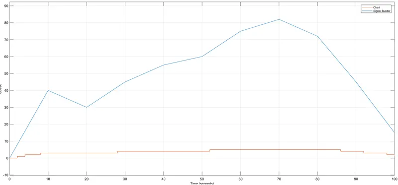
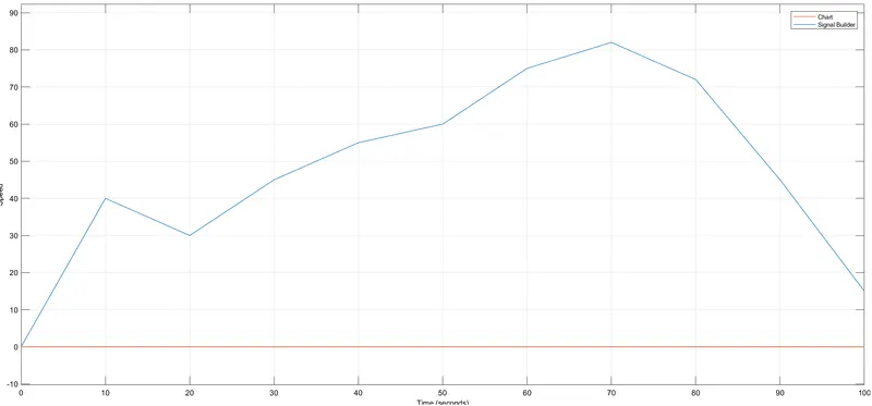
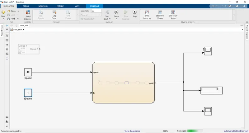
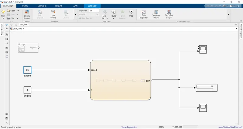
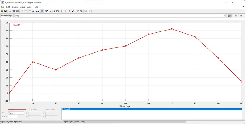
Give speed input while the simulation is running & display the gear number.
Understanding the model
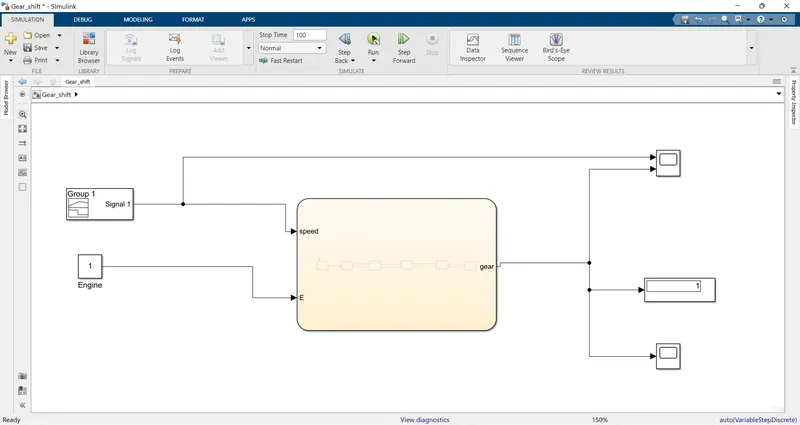
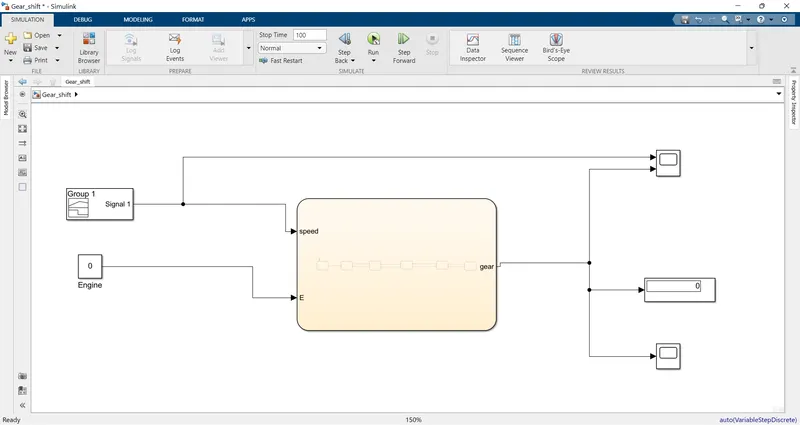
In this part of our problem, we have to model a gear mechanism and simulate it as per the given conditions. Let’s understand the model:
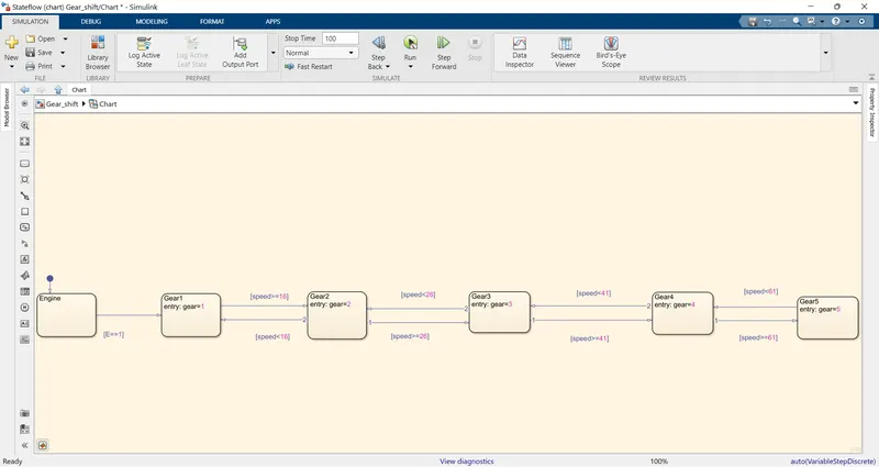
1) Again we’ll be working on Stateflow and hence we input the ‘chart’ block. In it, we place the Engine state first, so that the precursor to run a vehicle can be set as the start of the Engine.
2) Now as per our given set of conditions we’ll be creating 5 states corresponding to 5 gears. For the first gear we’ll state the speed to be between 0-15. Hence, whenever the speed goes above 0 and below 15 the first gear will be engaged.
3) The second gear shall be engaged at a speed of 16-25. The condition for the same has been mentioned in the transition. Similarly, the conditions for transition have been mentioned for each gear.
4) While running a vehicle the speed of the vehicle will be non-uniform in most practical conditions. Hence, when we provide transition conditions for the forward or increasing trend, we need to provide conditions for the reverse or decreasing trend as well. The same has been done by using two arrows between each gear state in opposite directions.
The inputs to the chart block here are the speed and engine blocks. The speed block can be depicted with a constant block or a signal builder whereas the engine block has been depicted with a constant block with 1 & 0 corresponding to the on and off state respectively. The output of the gear is connected to a display and a scope for the numeric values and plot of the output respectively.
The Model
https://drive.google.com/file/d/12uVVNpVl8oBitygxv4J-SNbpWxt4rb7O/view?usp=sharing
Inputs
Ouputs