Week - 4
Aim:
Q1-To implement control logic of a “washing machine” using Stateflow as per given sequence.
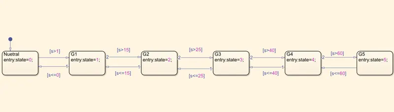
Q2- To make a Simulink chart for the “Gear shift” logic as per below conditions.
Objective:
Q1-Implement control logic of a “washing machine” using Stateflow as per given sequence:
- If the power supply is available, the system gets activated
- If the Water supply is not available, stop the process & indicate through LED
- Soaking time should be 200s followed by Washing time of 100s.
- Then rinsing happens for next 20s & dryer runs for 50s
After all the processes have completed turn on the finished LED
Q2-Make a Simulink chart for the “Gear shift” logic as per below conditions:
Speed Range(kmph) Gear
0 to 15 1
16 to 25 2
26 to 40 3
41 to 60 4
Above 61 5
Give speed input while the simulation is running & display the gear number.
STUDY1:
Stateflow:
Stateflow provides a graphical language that includes state transition diagrams, flow charts, state transition tables, and truth tables. You can use Stateflow to describe how MATLAB algorithms and Simulink models react to input signals, events, and time-based conditions.
Control logic:
Control logic is the part of a controller that defines how a reactive system responds to events or conditional changes.
Explanation:
I have build a "washing machine" using stateflow chart according to the given sequence.
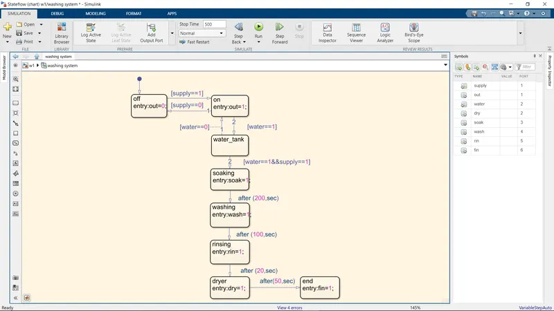
if the supply value is 1, the system get activated otherwise it will in off state.
if the water value is 1, the water tank will allow water for the process otherwise it won't allow.
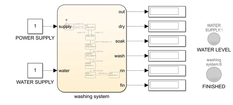
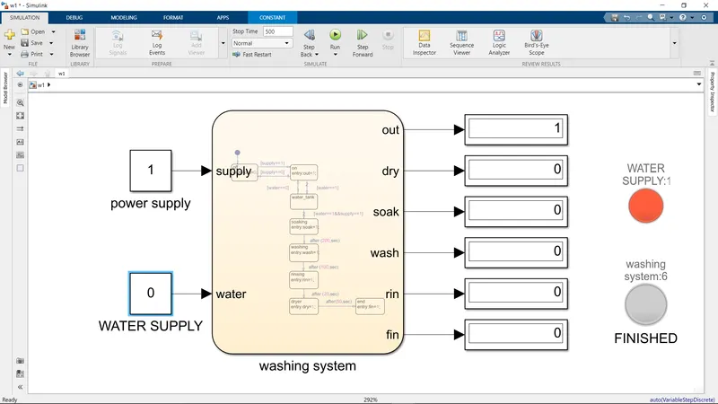
If the water supply is 0,the water level lamp will glow in red colour.the water level lamp is connected with water supply signal
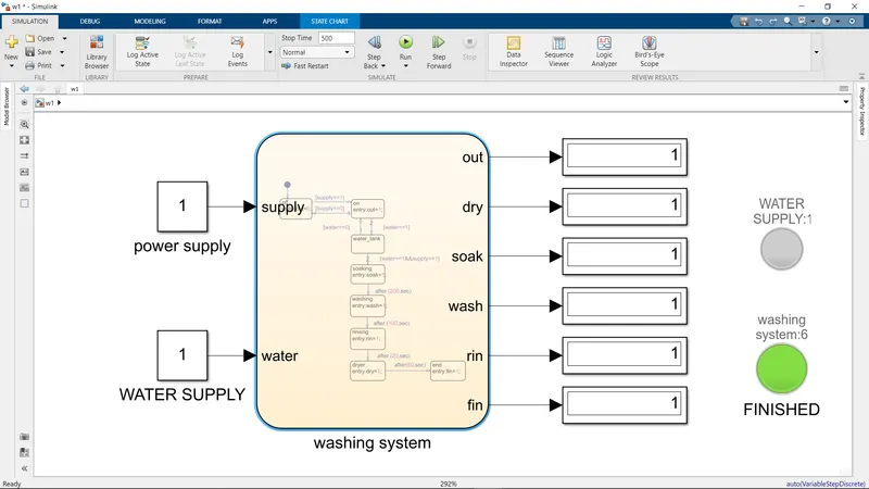
After all the process have been completed that means the finished lamp will glow in green colour.and the finished lamp is connected with the output of fin.
STUDY1:
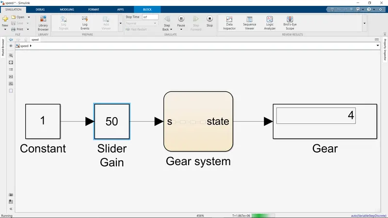
I have build a gear shift mechanasim as per the given conditions.
Explanation:
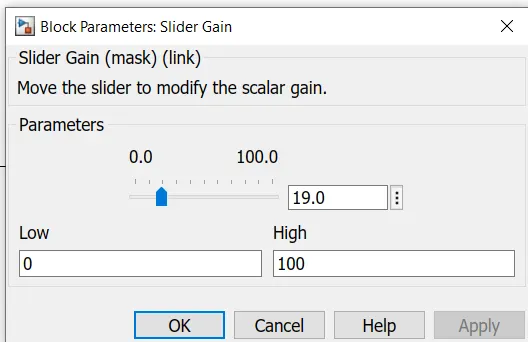
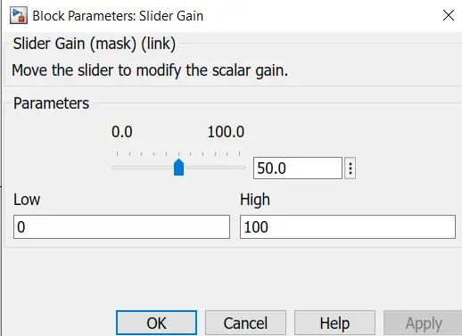
In the gear shift stimulation, i have used slider gain signal for speed variations
Slider gain:
The Slider Gain block performs a scalar gain that you can modify during simulation. Modify the gain using the slider parameter.
Stimulation:
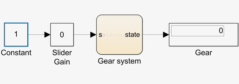
- The stop time of the stimulation is infinite because i have used slider gain signal,while running the stimulation i have to varry the speed ,according tp the speed the gear value will shown in the gear block.
OUTPUT:
STUDY1:
- The output for water supply zero ,the power supply only ON.
- The output for water supply 1 and full system.
STUDY2:
- I have given the speed of 50 in the slider gain,as per the given condition the gear value is shown in the gear block.
CONCLUSION:
Thus the control logic of a Washing machine and Gear shift using stateflow has studied and stimulated done with successfully.