Week - 4
1.Implement control logic of a “washing machine” using Stateflow as per given sequence:
- If the power supply is available, the system gets activated
- If the Water supply is not available, stop the process & indicate through LED
- Soaking time should be 200s followed by Washing time of 100s.
- Then rinsing happens for next 20s & dryer runs for 50s
After all the processes have completed turn on the finished LED
-----------------------------------------------------------------------------------
Blocks used:
- Slider switch
- Constant Block
- Chart (stateflow)
- Scope
- Lamp
Procedure:
- Insert Chart Block in Simulink environment.
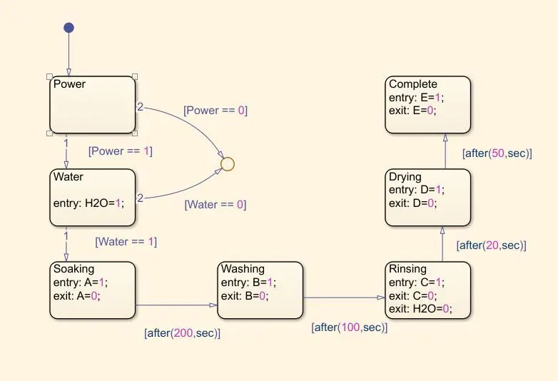
- Inside chart block, Define power supply and water supply states.
- Connect power supply to water supply with condition [Power == 1]. Power is the input signal we will receive form switch.
- Connect power supply and water supply states to a junction with condition [Power == 0] and [Water == 0]. This Implies that if either of power and water are not availabe further states wont be run through.
- Inside chart block Define other states or Soaking, rinside, drying etc and put entry and exit conditions.
- Connect water supply state to Washing block with condition [Water == 1].
- Further connect remaining states one after other with time delays as per condition. example: [after(20,sec)]
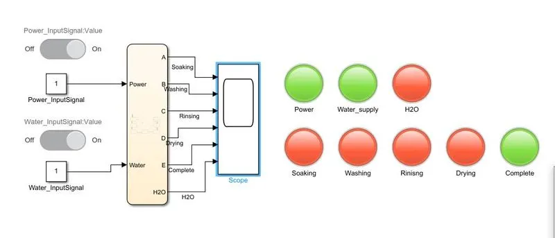
- In the Simulink environment insert 2 slider switch blocks and 2 constant blocks for Power supply and water supply.
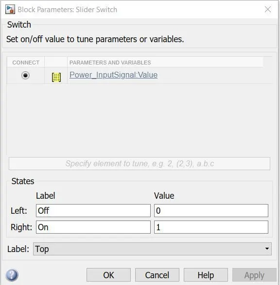
- In the slider switch parameter, define 1 constant for each power and water supply and define the on and Off values. This implies when slider switch block is off the constangt value will be 0 and vice versa.
- Connect both switch to Chart Block. Specify to what data the input is going. In the stateflow chart we use [Power == 0] and [Water == 0], hence the data will be either of the two.
- Insert scope block to visualise results of each states, as to at which second which state is active. (i.e. ny visualising the value of 1 and 0). The data for each scope should be specified. This data are the Variables A, B, C, D, E we use for defining entry and exit of states. Name each signal going to the Scope with its state.
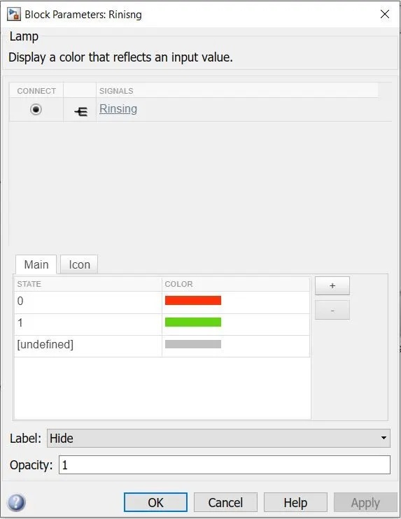
- Insert Lamps for each state, Input signals and actual water supply. Define Colour of Lamp when the signal shuffles from 0 and 1. Connect the lamp to a signal coming from chart to the scope.
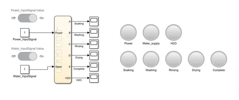
Block:
Stateflow:
Where the Power and water Supply slider switch are only then the further states will be achieved. If wither of 2 are off, The signal will end at a junction.
After each specified time frame the states will change.
Actual Water supply will end after the rinsing state.
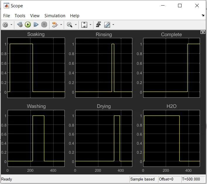
Results:
Each State is active during its time as per condition and inactive during the rest.
Each lamp Turns Green and Red in accordance with the Signals above. The Image shows the situation at the end of 1 cycle, where the Complete Lamp can be seen as green. The Water and Water Supply Blocks are green as well, But they indicate the switch. All other states are red. If Simulation is done Step wise, Each Signal turning red and Green as per the time frame can be witnessed.
H2O indicates the actual water supply in the washing machine as per the condition, which is it shuld stop after the Washing state.
2. Make a Simulink chart for the “Gear shift” logic as per below conditions:
Speed Range(kmph) Gear
0 to 15 1
16 to 25 2
26 to 40 3
41 to 60 4
Above 61 5
Give speed input while the simulation is running & display the gear number.
_______________________________________________________________________________
Blocks Used:
- Constant block
- Slider Gain
- Signal Builder
- Lamp
- Stateflow - Chart
- Custom Gauge
Procedure:
- Insert Chart block in Simulink environment.
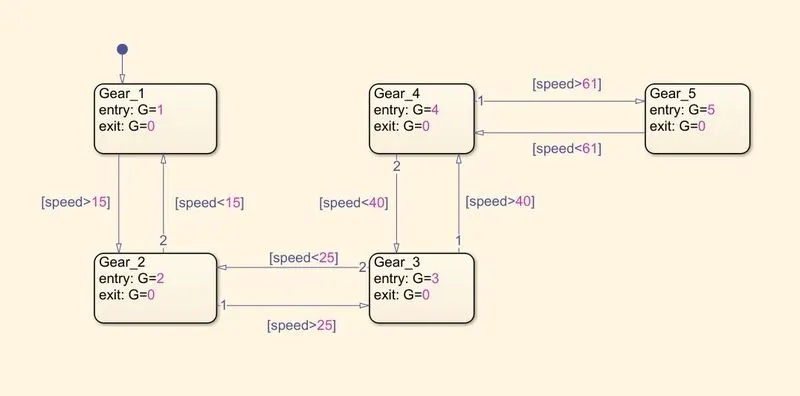
- Inside Chart block, create states 5 States.
- Inside each state define entry and exit.
- Connect each state and define the condition of state transition at arrows, example : [speed < 25]
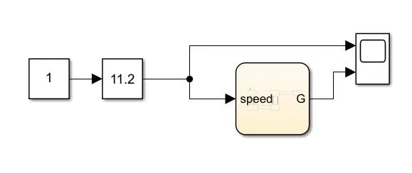
- In the Simulink environment, give input signal in form of slignal builer or slider gain.
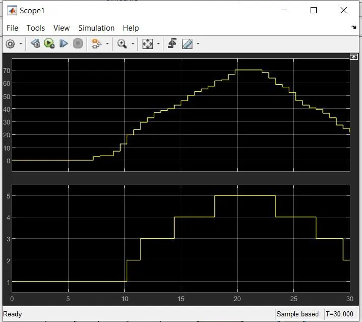
- Reaslise the result of the signla builder and Gear positions in the scope.
Block:
Block with use of Signal builder:
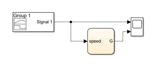
Block using Signal gain:
State Flow Chart:
Results:
By using Signal builder:
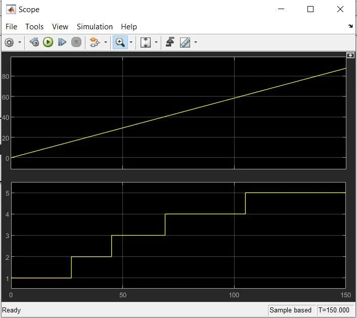
By using Signal Gain: