SIMULINK Week - 4
AIM:
1. Implement the control logic of a “washing machine” using Stateflow as per the given sequence:
- If the power supply is available, the system gets activated
- If the Water supply is not available, stop the process & indicate through LED
- Soaking time should be 200s followed by Washing time of 100s.
- Then rinsing happens for the next 20s & dryer runs for 50s
After all the processes have been completed turn on the finished LED
2. Make a Simulink chart for the “Gear shift” logic as per the below conditions:
Speed Range(kmph) Gear
0 to 15 1
16 to 25 2
26 to 40 3
41 to 60 4
Above 61 5
Give speed input while the simulation is running & display the gear number.
STATEFLOW BLOCK DIAGRAM FOR WASHING MACHINE:
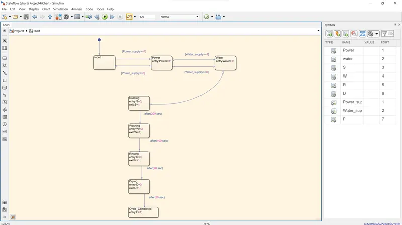
The process of a washing machine is performed in four stages such that:
- Soaking
- Washing
- Rinsing
- Drying
Soaking:
Soak Function or Pre-wash is used to dip clothes in detergent water to remove dirt from the clothes. In this function, customers need to select soak from a panel
Soak - This function is available with a wash timer, In 470 sec of washing 200 sec is soaked and 100 sec for the machine will wash the clothes as per the question.
The option called prewash indicated filling the drum with a certain water level and mix up with the detergent powder. All this option helps to wash out all the stains including the stubborn or dirt very well from the clothes. This is possible as we soak the whole clothes placed into the drum. Finally, drain the water without making a second thought.
Taking the amount of water is different for both front load and top load washers respectively. In the front-load washing machines, it is all up to the settings done by the single user. Whereas at the top load washers, there are water level sensors for filling the drum at a certain level and cleaning the entire load getting rid of stubborn stains successfully.

Washing:
It is a process that removes the dirt in the clothes whereas detergent powder was already added to the washing drum which helps to remove the stain.
At this particular time, the machine uses agitation which is for mixing both water and detergent, in turn moving the clothes all around the drum. Generally, the top load washing machines come with an agitator or impeller placed at the center of the tub.
While coming to front-load washers, it depends upon the rotation of the entire tub provided for enhancing better wash and cleaning the load ultimately. Moreover, the duration taken to complete the wash cycle depends upon the settings option chosen by the user. Always the heavy load enhances high duration. Small or limited load enhances less duration.
Rinsing:
The option called rinsing is known as the multi-talented option. During this particular cycle is on the flow, the soapy water is taken from the clothes. And all the fresh or pure water is sparkled on the clothing available in the tub. This particular rinse option is held responsible for taking soapy water out of the washer without facing any kind of difficulties. Finally, the agitation with plain water is considered the last step in the rinsing option.
Drying:
Drying is done to dry the entire clothes before getting to the end of the actual wash cycle. And these several washing machines are going to be spun at different speeds. In turn, the speed of one particular spin is calculated in revolutions per minute (rpm) respectively. This indicates the speed of the spin extracting the whole amour of water from the clothes making it dry very well.
This block diagram is done by the Stateflow process in that certain conditions need to be achieved.
Blocks were used in this condition are:
- Chart
- Constant
- Toggle switch
- Display
- Lamp
Chart:
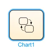
This block is mostly used to perform a graphical representation of a finite state machine consisting of states, transitions, and data. You can create a Stateflow chart to define how a MATLAB algorithm or a Simulink model reacts to external input signals, events, and time-based conditions.
Constant:

The Constant block generates a real or complex constant value signal. Use this block to provide a constant signal input. The block generates scalar, vector, or matrix output.
Toggle switch:
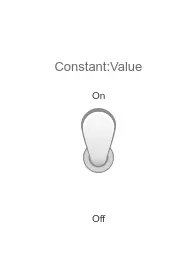
The Toggle Switch block toggles the value of the connected block parameter between two values during simulation. For example, you can connect the Toggle Switch block to a Switch block in your model and change its state during simulation.
Display:
The Display block shows the value of the input data. You can specify the frequency of the display. For numeric input data, you can also specify the format of the display. If the block input is an array, you can resize the block vertically or horizontally to show more than just the first element.
Lamp:

The Lamp block displays a color that indicates the value of the connected signal. To configure the Lamp block to provide the information you need during simulation, specify one or more states, which pair a signal value with a color for the Lamp block to display. As per the requirement, colors can be changed
Simulation Model:
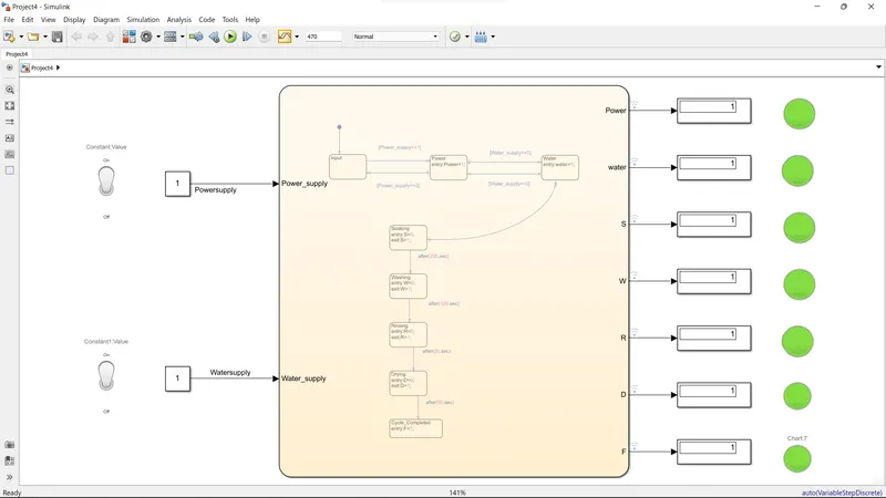
Inputs of Charts:
Whereas:
Power is an input of the washing.
Water is supplied for washing the clothes.
In Symbols inputs values are given Power_supply is 1; Water_supply is 2
S is Soaking
R is rinsing
W is Washing
D is a Dryer for clothes
F is the Final stage
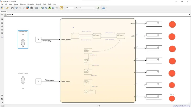
If the unit's power supply is turned off red as per the below figure.
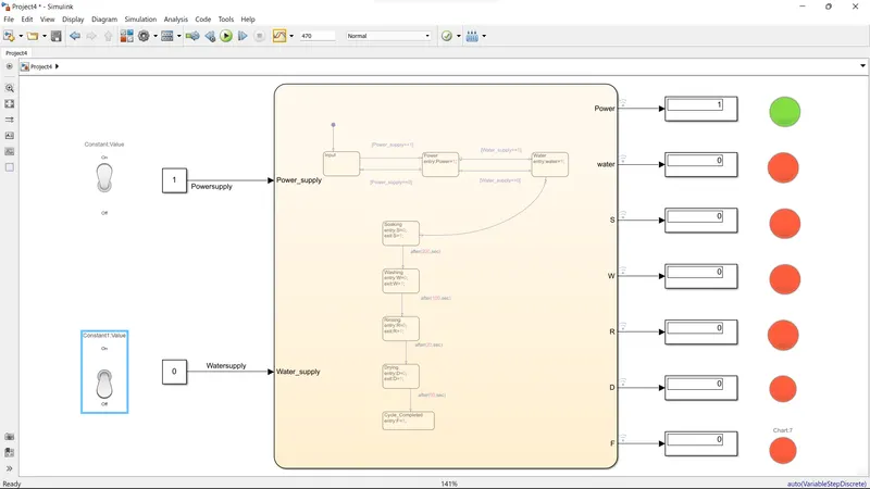
If the Condition that the Water supply is turned off but the power supply remains on then the below figure is shown:
2. Make a Simulink chart for the “Gear shift” logic as per the below conditions:
Gear shifting is a control that is used to attain various speeds in any system of machines/automobile etc.., according to the requirement.
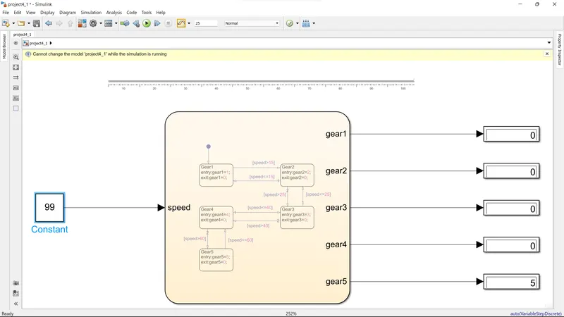
Here if the speed varies then the gear changes automatically according to the inputs passes to the blocks as shown below:
Speed Range(kmph) Gear
0 to 15 1
16 to 25 2
26 to 40 3
41 to 60 4
Above 61 5
Blocks were used in this condition are:
- Chart
- Constant
- Display
- Slider
Slider:

A slider is used to vary the value of the input by its movement of it.
inputs can be given as required here we gave 0 - 100 kph.
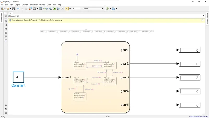
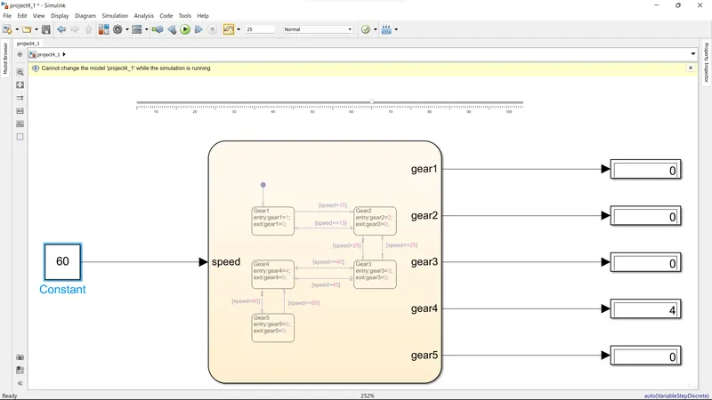
Here Slider and Constant have been connected, therefore if we change the value of the slider then constant changes.
Blocks Diagram of GEAR SHIFT:
Speed regulates then gear changes occured.
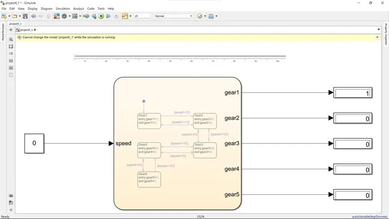
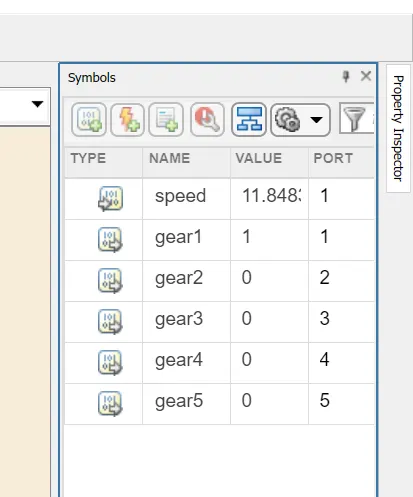
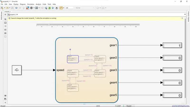
Condition 1:
Speed varies from 0-15 kmph where speed is 11.838 kmph.
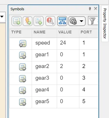
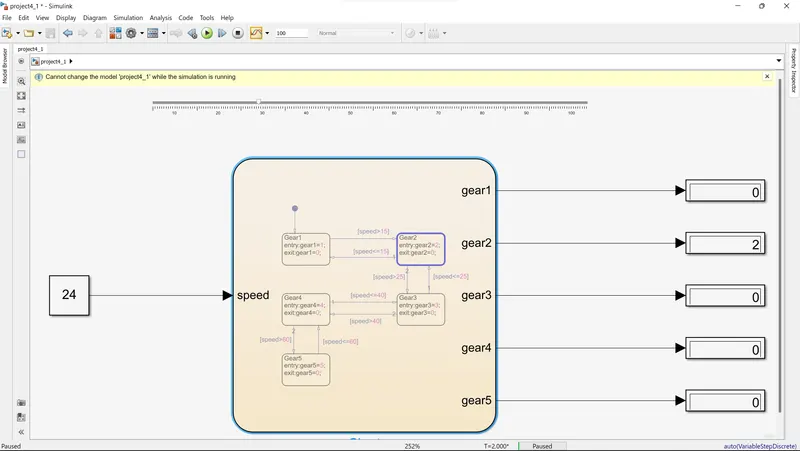
Condition 2:
Speed varies from 16-25 kmph where speed is 24 kmph.
Condition 3:
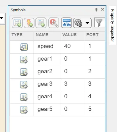
Speed varies from 26-40 kmph where speed is 40 kmph.
Condition 4:
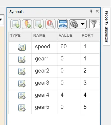
Speed varies from 41 - 60 kmph where speed is 60 kmph.
Condition 5:
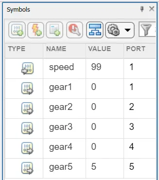
Speed varies from 61 above kmph where speed is 99 kmph.
Errors:
I can't able to connect the Inputs value in a chart then I recited that in the flow lines inputs names should be given then it automatically takes place.