Week - 4
- Implement control logic of a “washing machine” using Stateflow as per given sequence:
- If the power supply is available, the system gets activated
- If the Water supply is not available, stop the process & indicate through LED
- Soaking time should be 200s followed by Washing time of 100s.
- Then rinsing happens for next 20s & dryer runs for 50s
After all the processes have completed turn on the finished LED
Working Principle of Washing Machine:
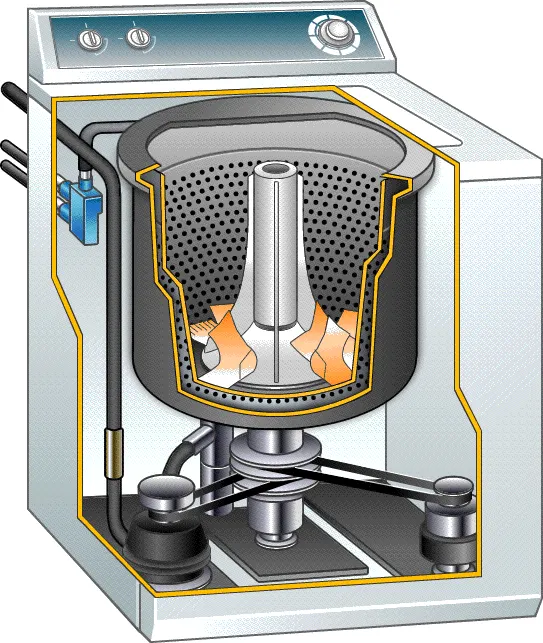
- An inner drum: This is where we put the laundry. One can notice that this drum rotates a bit when you touch it, and there are a lot of holes punched into it. These holes allow the water to come in and wash the clothes.
- Paddles: These are ridges that lie on the edge of the drum and help move your laundry around while being washed.
- Agitator: It is a paddle, more common in top-load machines, in the middle that helps turn the clothes around in the soapy water.
- The outer drum: This drum is not visible when you look inside the washer, but there is another drum that holds the water while the inner drum or agitator rotates. This part is completely water-tight to prevent your machine from leakage.
- Thermostat and heating element: These control the temperature of the water and heats the water to the specified temperature.
- Pump: This removes the water from the drum after the wash.
- Programmer: This controls the washing machine through all the steps from washing to rinsing and spin-drying.
- Pipes and valves: These allow the water in and out of the washer.
Simulink Model:
State Flow Diagram :
Operation :
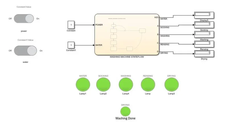
1. The input power supply source & water inlet to washine machine is declared using contant source block 0 & 1 represents ON & OFF respectively.
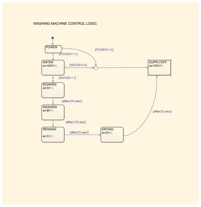
2. When both power and water input at stage of 1 , the soaking process will start and run for 200sec . Next to this process washing will start and hold for 100sec followed by rensing process for 20sec
3. After rensing it will pushed to drying stage and keep this process for 50sec
4. Then finally power gets off after draining all water used on rensing stage.
---------------------------------------------------------------------------------------------------------------------------------------------------
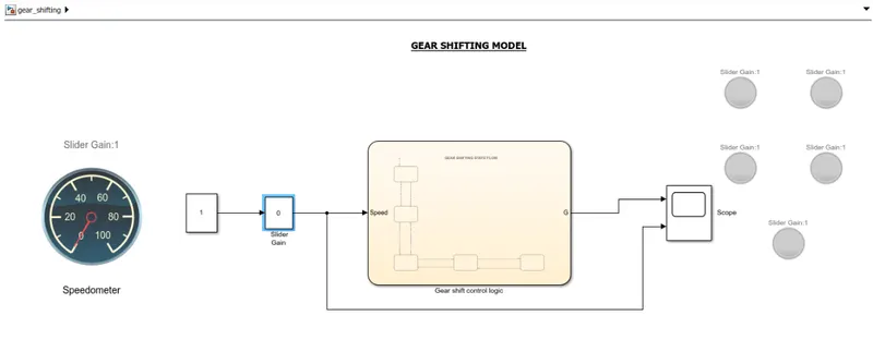
C2. Make a Simulink chart for the “Gear shift” logic as per below conditions:
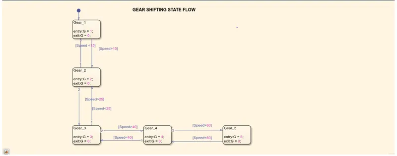
Speed Range(kmph) Gear
0 to 15 1
16 to 25 2
26 to 40 3
41 to 60 4
Above 61 5
Give speed input while the simulation is running & display the gear number.
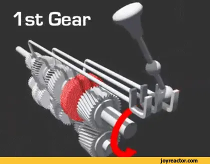
Working principle of Gear Mechanism :
Simulink Model :
Stateflow diagram:
Process Explanation :
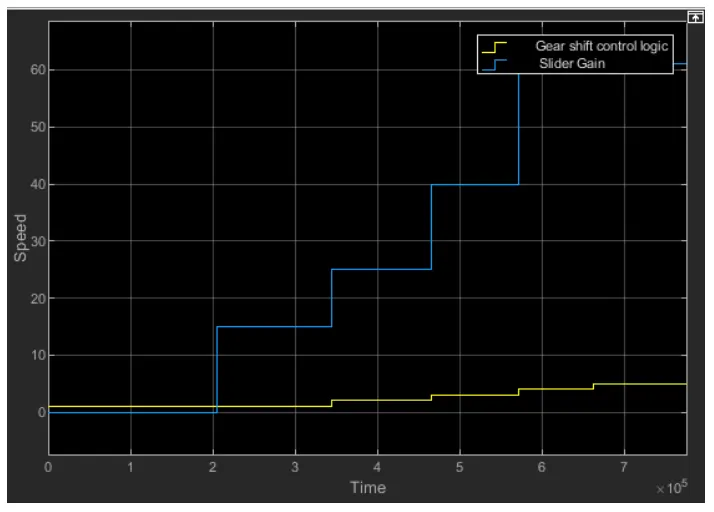
1. The slider gain provided to vary the input signal and used in simulink model (Neutral = 0).
2. Increase in speed can be seen in speedometer used , the stateflow module input given as speed get display over different gear shift / transmission
3. The gear shifting can be attained by speed input as varying the slider gain ex: 0-15kmph as gear 1 to max and etc.,
4. Then we can down the speed and downshifting the gears to zero position
Result :