Week -2
Q1. Make a Simulink model of Doorbell using solenoid block with the following details:
Objecive:
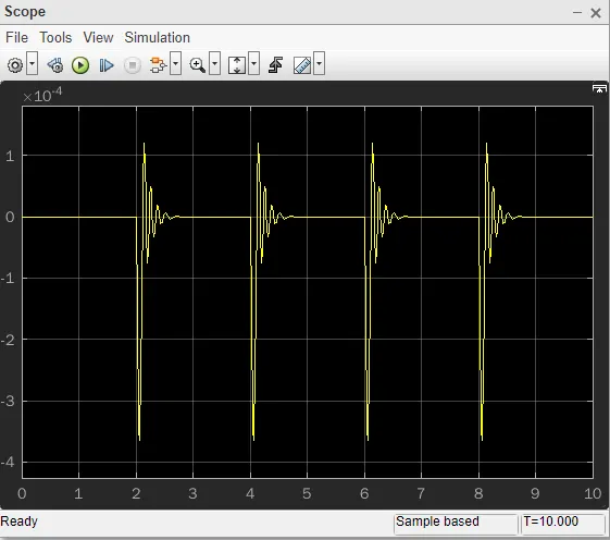
Create a situation where the switch is closed for 2 seconds and then released. Observe the physical movement of the plunger. (Door Bell).
Required blocks to create above model
1. Pulse Generator : Pulse generators are used primarily for working with digital circuits, and the equipments used to generate different waveform signals.
2. Simulink - Physical signal converter : The Simulink-PS Converter block converts the input simulink , signal into a physical signal. Use this block to connect Simulink sources or other Simulink blocks to the inputs of a Simscape physical network.
3. Battery : DC Power source to run a DC circuit to attain desired output signal.
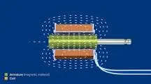
4. Solenoid : A solenoid is a device comprised of a coil of wire, the housing and a moveable plunger (armature). When an electrical current is introduced, a magnetic field forms around the coil which draws the plunger in. More simply, a solenoid converts electrical energy into mechanical work.
Model:
Result:
Explanation:
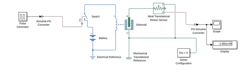
1. The switch block is used to controlled by a S-PS converter , it gets ON and OFF by exceeding threshold range.
2. Battery positive terminal connected to the switch and the other terminal of switch to coil of solenoid and closed with reference.
3. Solenoid plunger movement can be measured by motion sensor connected to R in solenoid and C connected to M.Reference.
4. The movement of plunger will be monitored with scope by switch ON and OFF with time of 2 Sec delay.
Q2. Use a thermistor to sense the temperature of a heater & turn on or turn off the fan as per the below conditions:
Objective:
Temperature source: 20 °C from 0 to 10 seconds, 27 °C from 10 to 30 seconds, 23 °C from 30 to 50 seconds
Fan conditions: ON if the temperature above 25 °C, OFF otherwise
Model:
Result:
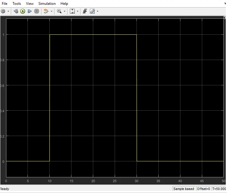
Explanation :
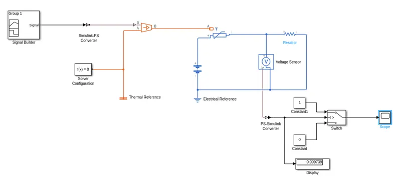
1. In this model we need Signal generator to produce signal with difference conditions related to time .
2. To set the below condition to signal generator by double clicking the block
a) At time of 0-10 sec value should be 293 Kelvin (i.e, 20 degree celcious)
b) At time of 10-30 sec value should be 300 Kelvin (i.e, 27 degree celcious)
c) At time of 30-50 sec value should be 296 Kelvin (i.e, 23 degree celcious)
3. Controlled thermal source provides thermal energy . So the temperature PS need to connect with Port S of Thermistor . Porrt A and Port B will have some greater values and temperture difference .
4. And the thermistor connected to a Resistor to limit a current flow from the battery and the negative terminals connected to reference .
5. Next step we have to control the Fan at specific temperature so we need to insert a Switch block and input as constant source i.e., 1 & 0 . So the Voltage sensor measures the variation of voltage across thermistor respective to thermal energy variation .
6. Voltage signal connected to PS-simulink converter and the same to switch then output can be simulate through scope block.
7. Condition once temperature reach 298 Kelvin / Voltage threshold the switch get ON if reduce it gets OFF. In our model we given a signal 300Kelvin at 10-30sec then the switch get ON and FAN will run.