Week - 4
- Implement control logic of a “washing machine” using Stateflow as per given sequence:
- If the power supply is available, the system gets activated
- If the Water supply is not available, stop the process & indicate through LED
- Soaking time should be 200s followed by Washing time of 100s.
- Then rinsing happens for next 20s & dryer runs for 50s
ANS:
A washing machine is a laundry machine, clothes washer, washer, or simply wash is a home appileance used to wash laundary The term is mostly applied to machines that use water as opposed to dry cleaning (which uses alternative cleaning fluids and is performed by specialist businesses) or ultrasonic cleaners. The user adds laundary detergent which is sold in liquid or powder form, to the wash water.
STAGES OF WASHING MACHING:
LET , us now undergo the stages of a washing maching machine which in turn helps you to understand better and pick the option depending on the bASIS of your need successfully.
- PREWASH
- WASHING
- RINSING
- SPINNING
STATEFLOW CHART:
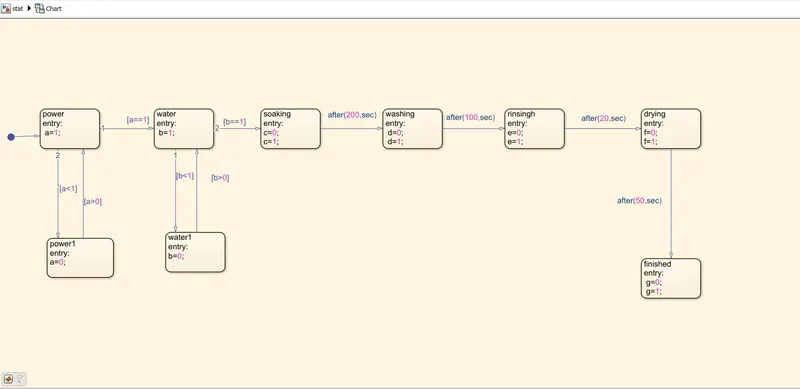
modeling of washing machine in simulink :
these are the following things we need for modelling the subs system of washing maching logical block setting:
- toggle switch
- constant
- lamps
- display
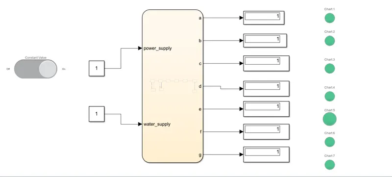
1 POWER ON:
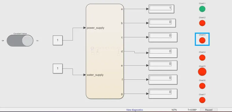
2. WATER SUPPLY ON:
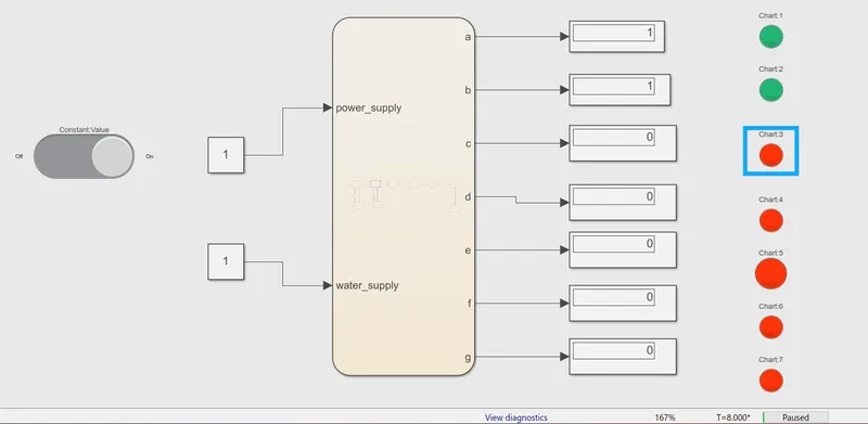
3. SOAKING:
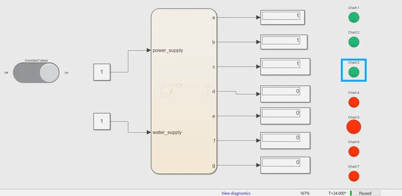
4. WASHING ON:
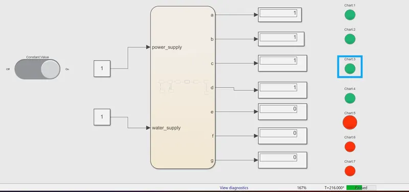
5. RINSING:
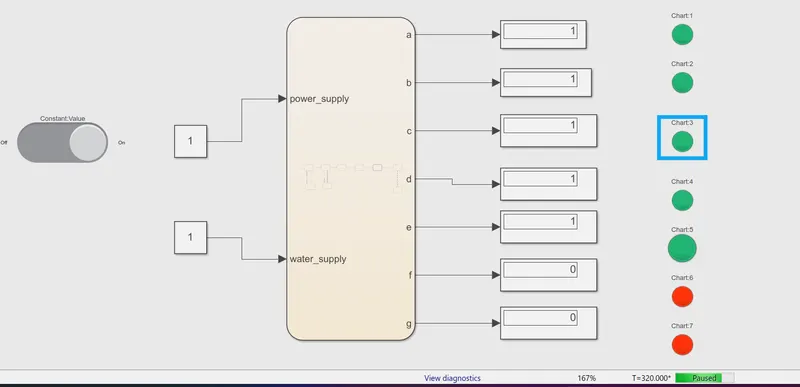
6. DRYING:
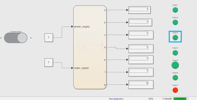
7. END PROCESS:
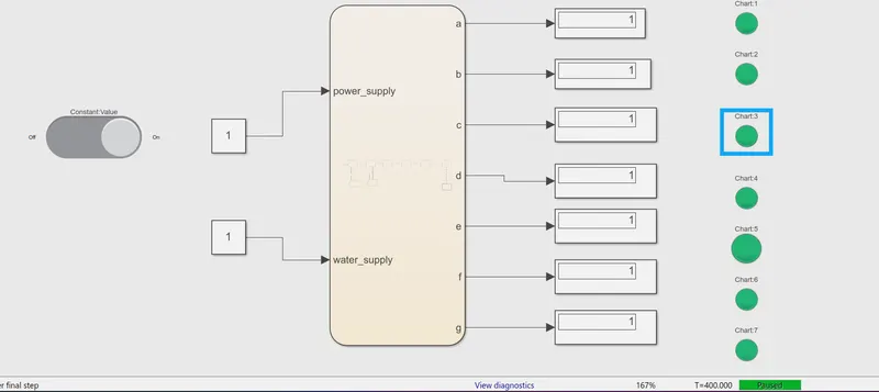
JUST ACCORDING TO EVERY STEP WE DEFINE HERE EXECUTE ACCORDINAR.
2. Make a Simulink chart for the “Gear shift” logic as per below conditions:
Speed Range(kmph) Gear
0 to 15 1
16 to 25 2
26 to 40 3
41 to 60 4
Above 61 5
Give speed input while the simulation is running & display the gear number.
ANS:
Automatic transmissions traditionally have had a straight pattern, adopting the classic P-R-N-D gate, with "P" being to the front, topmost position (or "P" all the way to the left on a column-mounted shifter); the corresponding shift positions being:
- P = Park - transmission is mechanically locked in position for parking, via a parking pawl.
- R = Reverse - reverse motion
- N = Neutral - no drive applied to the wheels with the engine running
- D = Drive - forward motion with fully-automatic operation in all gears.
All automatics use some sort of manual override of the transmission, with numbered positions in descending order marked below (or to the right) of "drive", which will prevent the transmission shifting to a gear higher than the selected, but maintaining automatic operation between all lesser numbered gears. Such gates will appear as P-R-N-D-3-2-1 for example
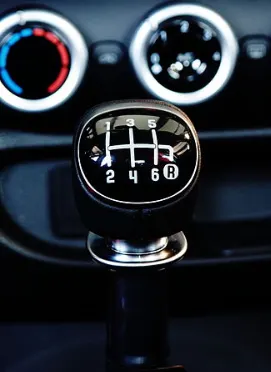
Before we go into simulink for the transmission box simulation w need to follow the below conditions for the setup .
speed Range (km) Gear
0 to 15 1
16 to 25 2
26 to 40 3
41 to 60 4
above 61 5
and by doing so we do that in a coded pttern in the state flow chat wich we get to see below:
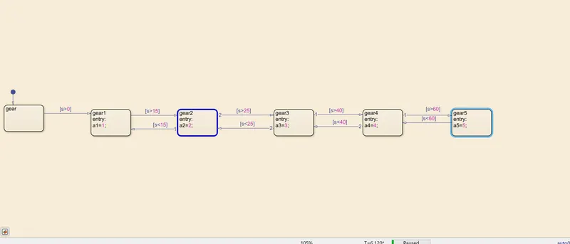
these are the following block setuo did we need for the setup:
- state flow chart
- slider
- constant
- dislpay
- lamp
and the output is just as similar it is
O TO 15 1ST GEAR
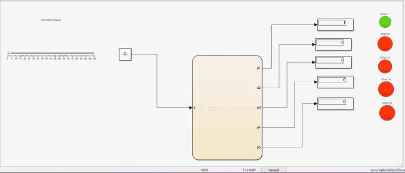
16 TO 25 2ND GEAR
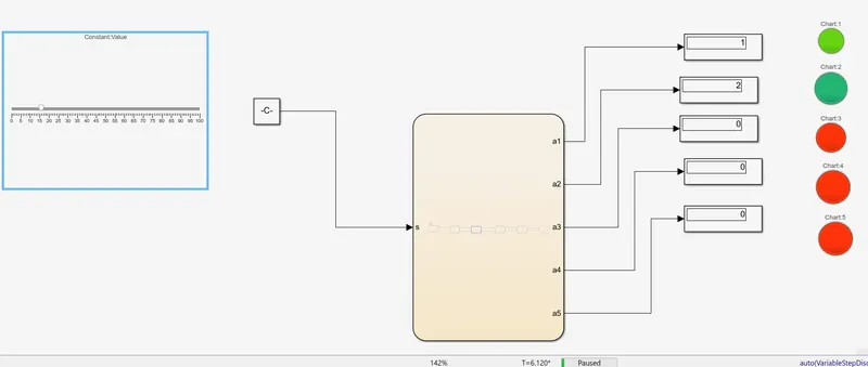
25 TO 40 3RD GEAR
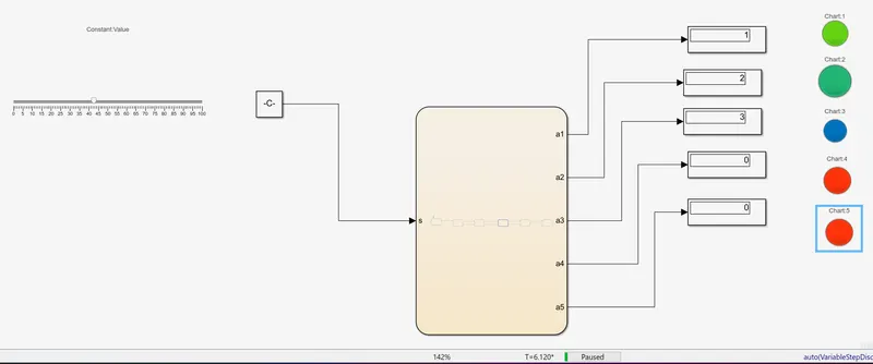
41 TO 60 4TH GEAR
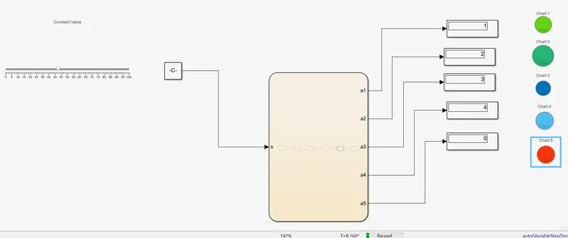
ABOVE 61 5TH GEAR
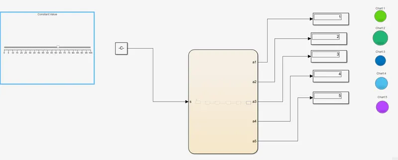
and that's how we did the gear shift logic in the simulink. As we can see lapm is it according to the gear it shows and the gear is according to the gear it show and the gear is at the current running according to the speed we selected from slider.