Week - 4
AIM : TO implement control logic of a washing machine using stateflow in simulink.
OBJECTIVE :
Here, the main objective is to implement the control logic of a washing machine using stateflow as per given sequences :
- If the power supply is available , the system gets activeted.
- If the water supply is not available , stop the process and indicate through LED.
- Soaking time should be 200 sec followed by washing time of 100 sec.
- Then rinsing for next 20 sec and dryer for 50 sec.
- After finishing of all processes turn on the finished led.
THEORY :
STATEFLOW :
- Stateflow provides a graphical language that includes state transition diagrams , flow charts , state transtion tables , and truth tables .
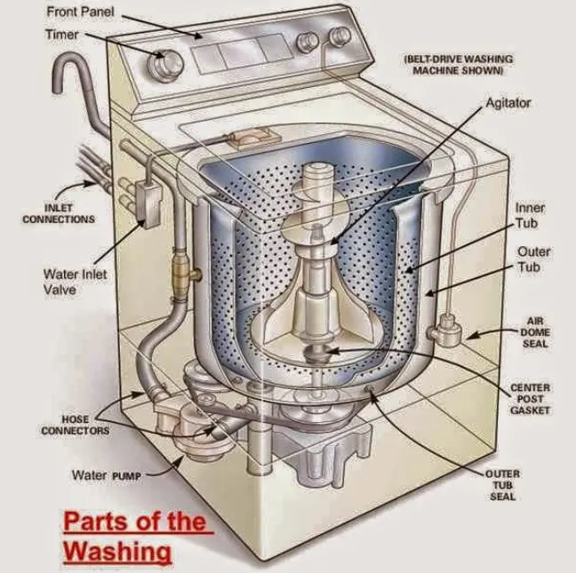
Working Principle of washing machines :
The working principle of a washing machine is centrifugation. Centrifugation is seperation process that uses the action of centrifugal force that uses the action of centrifugal forces to proote accelerated setting of particles in a solid-liquid mixture .
MODEL :
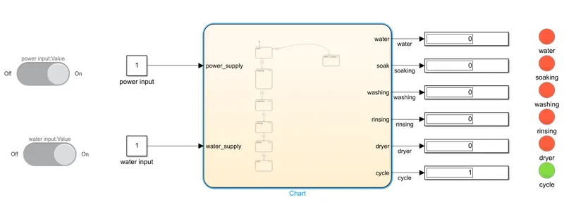
BLOCK USED :
- Slider switch
- constant block
- chart
- disply
- lamp
Explanation :
- Creating chart :
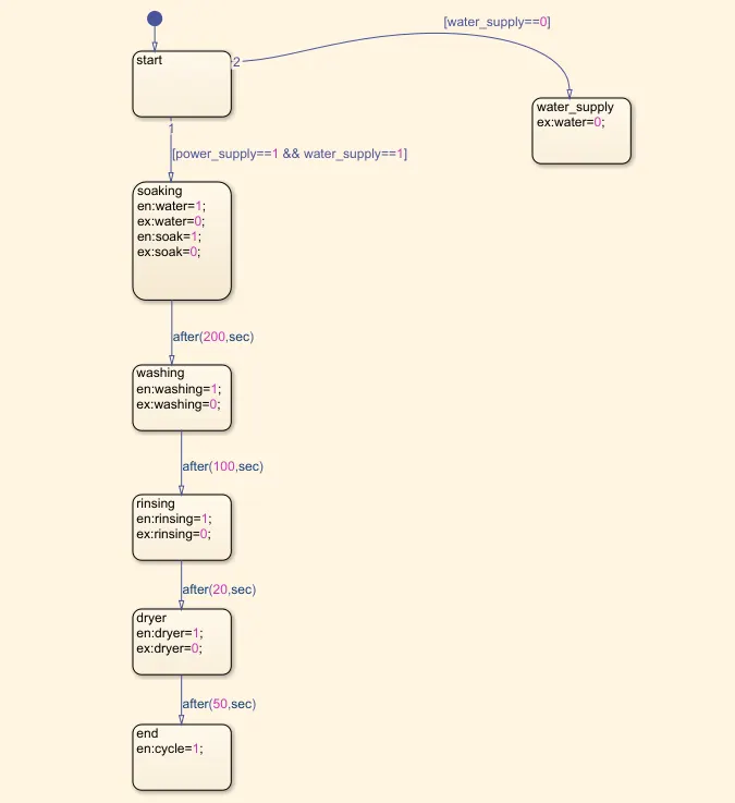
Here for given conditions ,we have given water_supply and power_supply as input of the chart.
And water,soak,washing,rinsing,dryer,cycle as output of the chart.
- Water_supply is connected to constant which is connected to slider switch through which we can give 'ON'/'OFF' conditions.
- Power_supply is connected to constant which is connected to slider switch through which we can give 'ON'/'OFF' conditions.
- Output from the chart is connected to display which shows the outputs.
- output is connected with bulb which indicates the process by colour of bulb which is green for running process and red for end of the process.
LOGIC :
- when we give input through slider switch ie 'ON'/'OFF' ,it will define value in constant block ie '1'/'0' for respective conditions.
- Now if we take value of water_supply is 0 then it which passes to state flow logic which will not start the process according to our requirement.
- now if both switches are 'ON' ,then process start and it will takes 200 sec of soaking.
- After 200 sec of soaking ,it will take 100 sec of washing and then rinsing happen for 20 sec and drying for 50 sec.
- At end of process the bulb will indicate green signal which means that the process is completed sucessfully.
OUTPUTS :
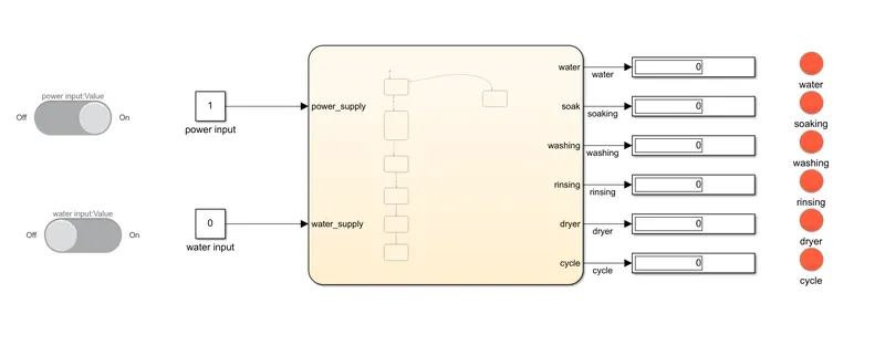
If water supply supply is not available and power is available :
After competion of all process :
CONCLUSION :
- If we power is on and water is not supplied then it will indicated red light.
- If both power and water supply is available then it will indicate green light.
Here given below is link for simulink model,
https://drive.google.com/file/d/1wzZIMbiEISge8ZV56n2tFcWuIIaPdL9D/view?usp=sharing
************************************************************************************************************************************************************************************************************************************************************************************************************************************************
AIM : To make a simulink chart for gear shift logic for given conditions.
OBJECTIVE :
- To make a simulink chart for gesr shift logic for given conditions:
Speed Ranges (kmph) Gear
0-15 1
16-25 2
26-40 3
41-60 4
Above 61 5
- Giving speed input while the simulation is running and displaying the gear number.
MODEL :
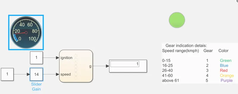
BLOCK USED :
- custum gauge : To indicate speed .
- Slider gain : it acts as throttle to increase or decrease of speed.
- Lamp : To indicate gear position .
- constant : To multiply with the slider gain .
- Chart.
Chart:
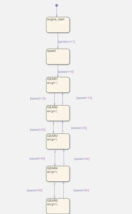
EXPLANATION :
- Here the custum gauge is connected to slider gain which is given as input to the chart .
- output of chart is connected to display ,which shows the position of gear which is then indicated through lamp.
- According to given data the range of speed and gear position are as below:
- For first gear ,speed is 0-15kmph.
- For second gear , speed is 15-25 kmph.
- For third gear, speed is 25-40 kmph .
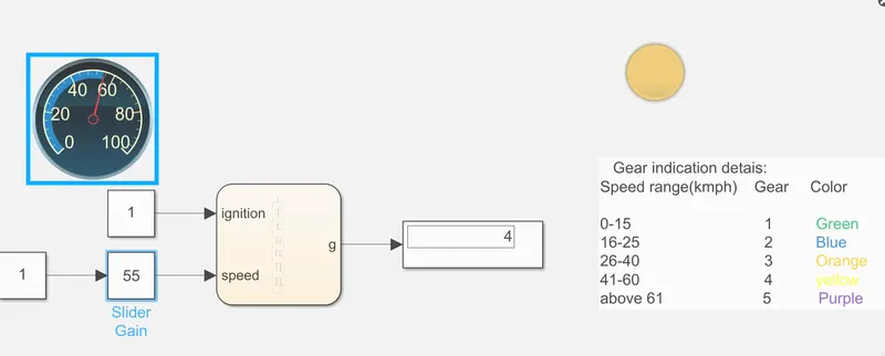
- For fourth gear , speed is 40-60 kmph.
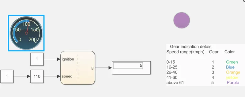
- For fith gear , speed is above 60 kmph.
OUTPUTS :
FIRST GEAR :
SECOND GEAR :
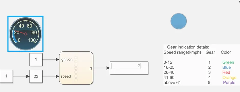
THIRD GEAR :
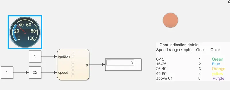
FOURTH GEAR :
FIFTH GEAR :
CONCLUSION :
- Here we have display the postion of gear by different colours.
- Outputs of gear speed according to speed of car is shown.
Here given below is link for simulink model,
https://drive.google.com/file/d/1i2256kfgn5iQcO4bhHcKe6vBfDSn_asY/view?usp=sharing