Week - 4
Q 1:
Aim :- Implement a control logic for washing machine and Gear shifting of automobile using stateflow chart in Simulink.
Objective :-
To Implement a control logic of a “Washing machine” using Stateflow as per the given sequence:
-If the power supply is available, the system gets activated
-If the Water supply is not available, stop the process & indicate through LED
-Soaking time should be 200s followed by Washing time of 100s.
-Then rinsing happens for the next 20s & dryer runs for 50s
-After all the processes have completed turn on the finished LED
Washing machine
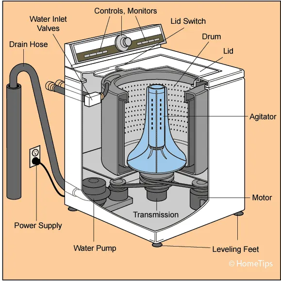
Basic Principle of washing machine: The machine which is capable of handling various tasks like washing, rinsing, drying, soaking within short period of time. All the task performed by the machine is based on centrifugation. It is a separation process which uses centrifugal force to promote accelerated settling of particles in solid-liquid mixture.
Input Conditions :- The different states of washing machines
Soaking - 200sec (0-200sec)
Washing - 100sec (200-300sec)
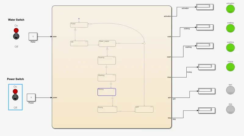
Rinsing - 20sec (300-320sec)
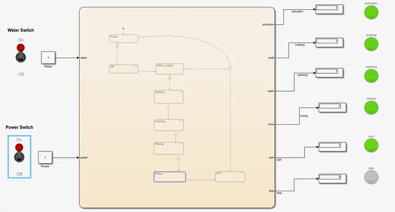
Drying/Spinning - 50sec (320-370sec)
Completed/ Stop the machine
Blocks used in the simulink model are as under;
Stateflow Chart :- For showing control logic in the washing machine model.
Display Block :- This block is used for displaying the output result of given logic.
Constant Block :- This block is used to give any constant/fixed value as input.
Toggle switch :- The Toggle Switch block toggles the value of the connected block parameter between two values during simulation.
Lamp :- Display a color that reflects an input value
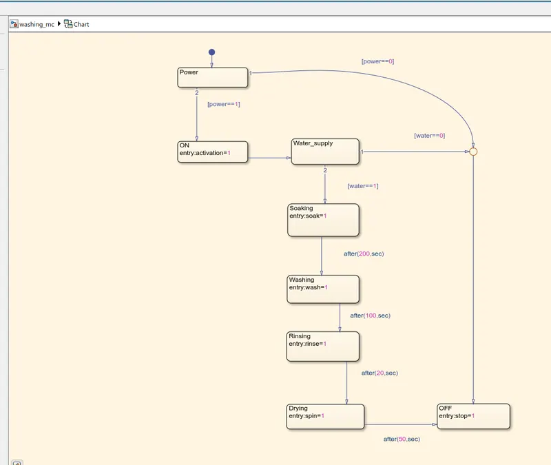
Stateflow Logic Chart :-
Explanation :-
-Initially, we have created power state and after going through the power state condition [power==1] means if power is there, it goes to second state (ON state). If power is not detected, means it goes through condition [power==0] and it further goes to OFF state condition.
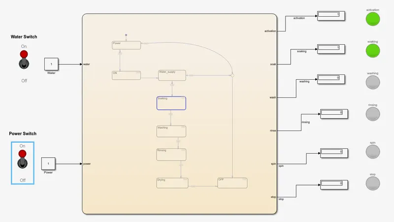
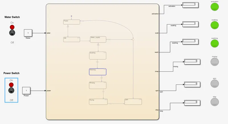
-when the power is detected, second state (ON state) got activated and it goes to third state i.e. Water_supply. After going through the third state (Water_supply), it goes through water condition. That means, if [water==1] condition satisfied, then it goes to soaking state for soaking operation for 200 sec. If [water==0] condition got satisfied, then it goes to OFF mode where machine stopped and stop lamp got activated. When soaking operation done for 200 sec, it got shifted to washing state and washing is done for 100 sec. After washing state, it goes to rinsing state for 20 sec where rinsing operation works. After rinsing state got completed, it goes to drying/spinning state for 50 sec where spinning/drying process works for drying the clothes.
-After drying / spinning state got completed, then machine goes to OFF state confirming it has follwed all the washing steps and
washing got completed for clothes and machine got stopped.
Different conditions in which above washing machine model worked is as under:
1) Water supply OFF & Power supply OFF
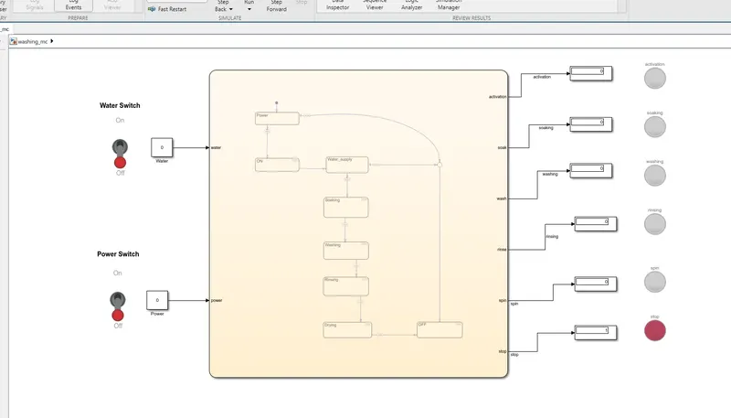
2) Water supply OFF & Power supply ON
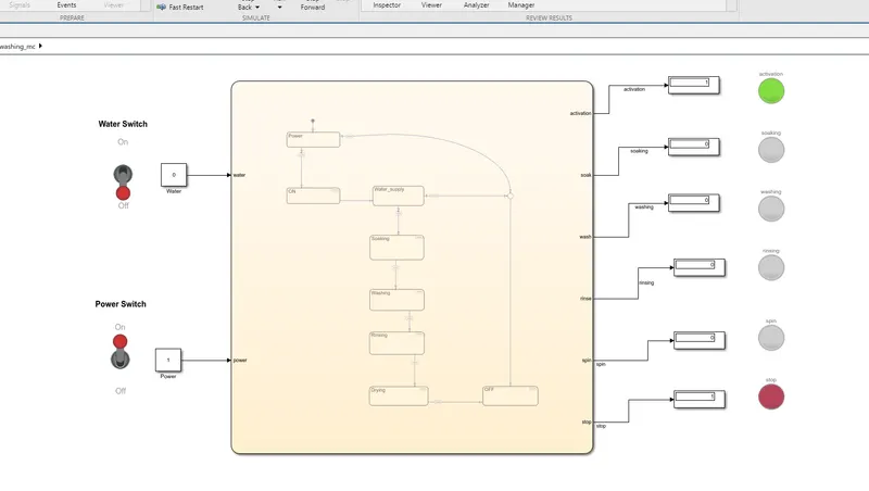
3) Water supply ON & Power supply OFF
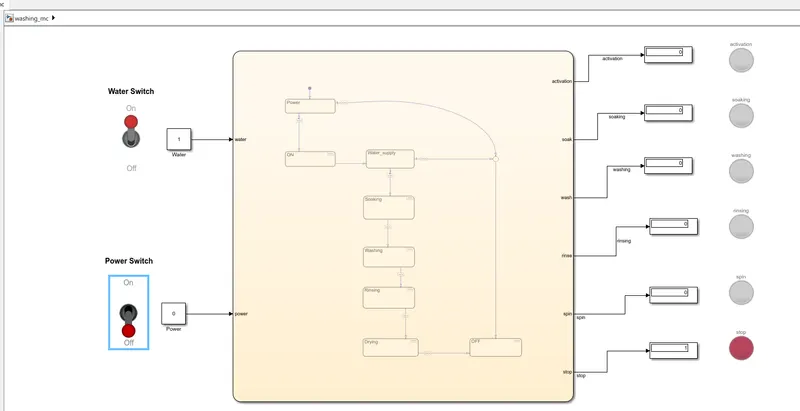
4) Water supply ON & Power supply ON
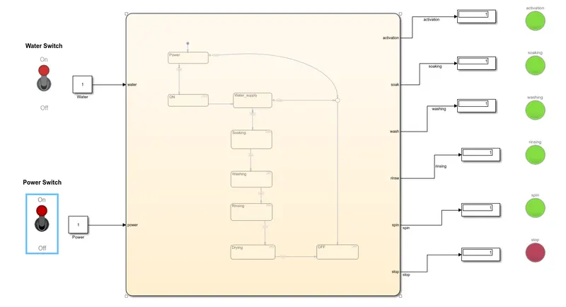
Different Stages of Washing machine working is as under:-
1) Soaking Process
2) Washing Process
3) Rinsing Process
4) Drying Process
RESULT:
Thus the control logic of the washing machine using the state flow is performed.
Q 2:-
Make a Simulink chart for the “Gear shift” logic as per below conditions:
Speed Range(kmph) Gear
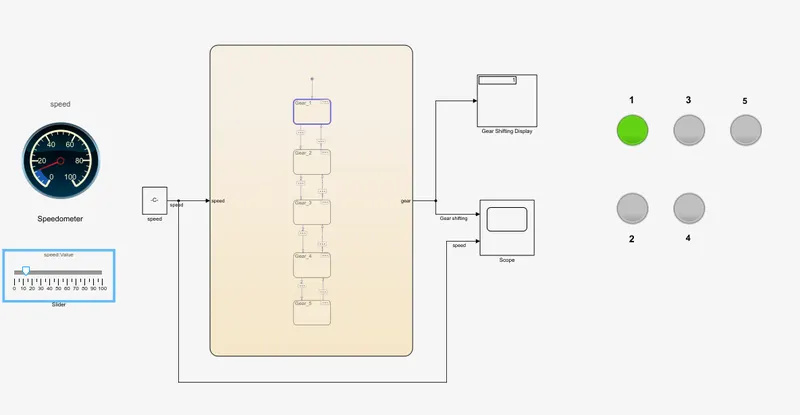
0 to 15 1
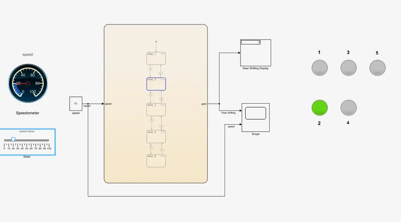
16 to 25 2
26 to 40 3
41 to 60 4
Above 61 5
Give speed input while the simulation is running & display the gear number.
BLOCKS USED IN THE MODEL:
Constant – To multiply with slider gain
Slider gain – Act as throttle to increase the speed
Lamp – For indicating gear number
State Flow – Gear shifting logic
Scope – For the graph of speed vs gear shift
Custom gauge – For representing speedometer of the vehicle
PROCESS:
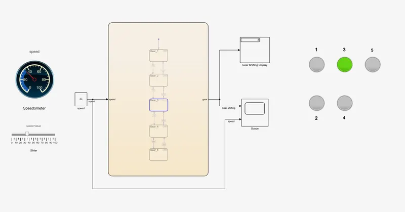
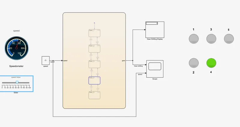
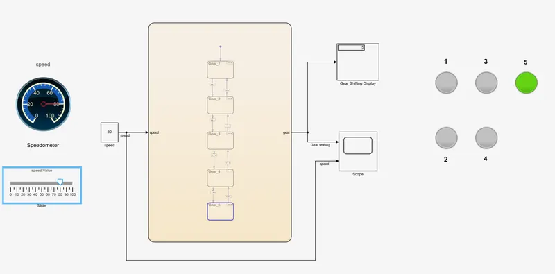
-The initial position of slider is at 0. When we increase the speed, the input is given to state flow chart where it checks the input speed and displays the gear number.
-According to given data, first gear speed range is (0-15Kmph), second gear speed range is (15-25Kmph), third gear speed range is (25-40Kmph), fourth gear speed range is (40-60Kmph) & fifth gear speed range is (greater than 60Kmph). The speed is decreased by downshifting of gear.
GEAR SHIFTING MODELS AT VARIOUS SPEED LEVELS:
1) 1st GEAR
2) 2nd GEAR
3) 3rd GEAR
4) 4th GEAR
5) 5th gear
RESULT:
After performing various calculations the simulink model is submitted to give the accurate result. Thus the Simulink chart for the “Gear shift” logic is made using state flow and the results are displayed.