Week - 4
Answers:
1.Control logic of a Washing Machine:
Washing machine is a device used to carry out various tasks such as soaking,Washing,Rinsing and drying with a centrifugal force action in a certain time duration.
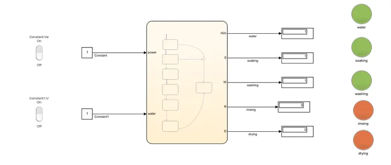
here, using a stateflow we are representing the various stages of working in a washing machine.now few default blocks are been taken and given various tasks such as power,water,soak,wash,rinse and dry.The conditions are provided like where 1 indicates conduction with a time duration .when supply is 0 the working gets stoped and indicator shows red.simularly during working condition the lamp indicates green colour.After each working and time duration the next working is been carried out.
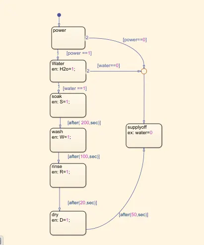
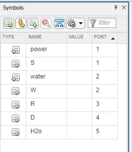
This operation is carried out by,
- When the power supply is given then the system it gets activated.
- when the water supply is not provided the process gets stop and the LED indication is shown.
- If the supply is available the clothes are added and water starts filled and they are soaked for 200sec
- After soaking of the cloths they are been washed for about 100sec.
- Followed by rinsing which is carried out for next 20sec.
- After rinsing the water is been drained out.
- Then dry is carried out for about 50sec after the work is done the LED indicates that the work is been completed.
- The symbol tab indicates the input and output ports.
- In the flow chart displays are added to the output ports and input are provided with constant blocks which is linked with a switch set.
- When the switch is ON it gives 1 simularly ,when it is Off it gives 0 value to the constant blocks.
- The Displays are been connected to the lamps with various operations.
- when the lamp is Off it shows Red and when its On it shows Green indication.
CONCLUTION:
Hence by this the working of a washing machine using stateflow is been shown.
2.Simulink chart for the Gear shift:
The gear shift is been explained below:
- The default transistion is been taken from the menu and five gear is been provided with various conditions.
- These blocks are named as GEAR1,GEAR2,GEAR3,GEAR4 and GEAR5 and inter conected with certain gearing conditions.
- The conditions are when,
- speed > 0 it goes to G=1,
- speed >15 it goes to G=2,
- speed > 25 it goes to G=3,
- speed > 40 it goes to G=4,
- speed > 60 it goes to G=5.
simularly when the value reduces the gear changes from 5,4,3,2,1.This condition is given as
- speed < 60 it goes to G=4,
- speed < 40 it goes to G=3,
- speed < 25 it goes to G=2,
- speed < 15 it goes to G=1.
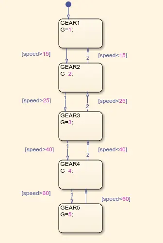
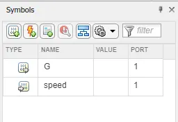
hence symbol tab shows the input and output ports.
FLOW CHART:
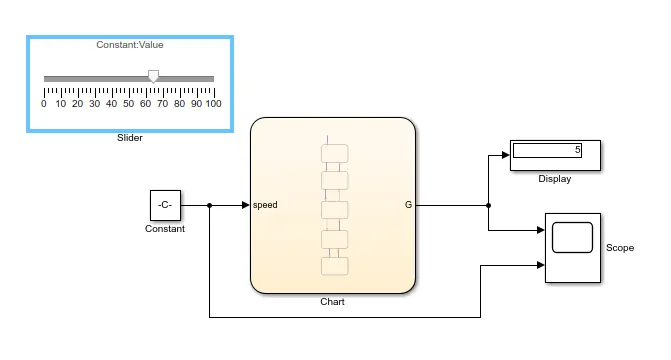
- In this after creating the conditions external blocks are added to give input and see the output .
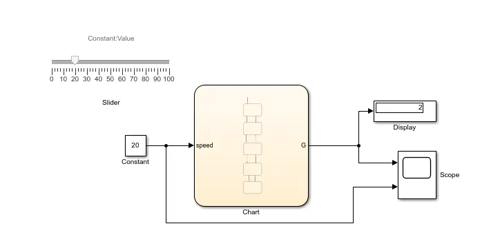
- Here a constant block and a slider is been taken, where the constant block is been linked with the slider.
- Then the output is been seen through a display and scope.
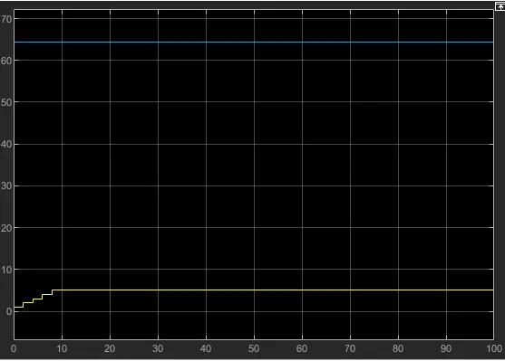
- By changing the slider value the gear is been changed and it is been seen in the display.
Some of the conditions are been shown below,
- In this the slider value is been changed to 20 which is the speed the gear changes from 0 to 2 which is shown in the display and scope.
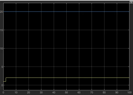
- In this same as above the slider value is been changed to 50 which is the speed the gear changes from 0 to 4 which is shown in the display and scope
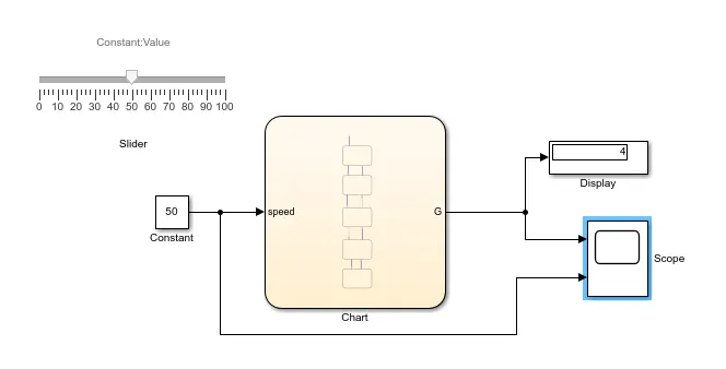
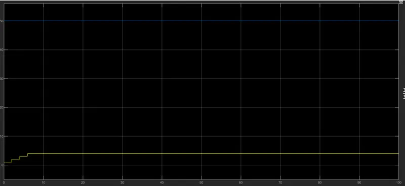
- This is for speed of >60 which goes to gear 5.
CONCLUTION:
Here Simulink chart for the Gear shift logic and speed input while the simulation is running and the gear number display is been shown.