Week - 4
ANS:1
AIM:
To Implement control logic of a “washing machine” using Stateflow as per given sequence:
- If the power supply is available, the system gets activated
- If the Water supply is not available, stop the process & indicate through LED
- Soaking time should be 200s followed by Washing time of 100s.
- Then rinsing happens for next 20s & dryer runs for 50s
After all the processes have completed turn on the finished LED
Washing Machine:
Washing machine is the machine which is used to wash the various types of clothes . It can be manual or automatic.
There ate several states/cycle Followed by washing machine to wash the cloths.
e.g-Soaking,Washing,Rinsing,Drying etc
To Implement control logic of a washing Machine using statefilow in simulink below blocks are required
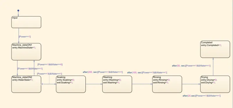
1) Chart:
Chart is a graphical representation of a finite state machine consisting of states, transitions, and data. We can create a Stateflow chart to define various state of a state machine.
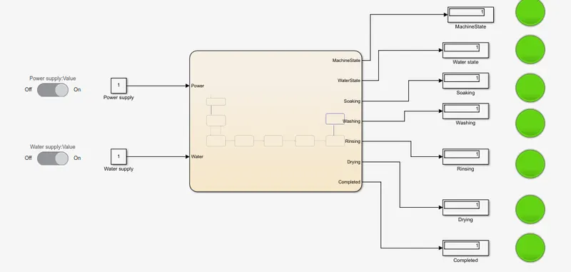
Here Various state of washing machine (e.g Soaking,Washing,Rinising and Drying ) Represented with specified time Delay.
2) Constant & Switch Block
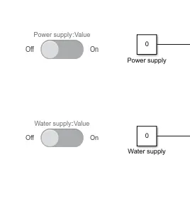
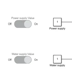
The Constant block generates a real or complex constant value signal. Use this block to provide a constant signal input.
In this model Two 'constant' block are used For Power supply input & Water supply input which further are Followed by "Switch Block'
When switch is On The constant block value shows 1 and when switch OFF constant block value is 0
3)Display & Lamp Blocks:
The 'Display' block shows the Result of the input data as output result from Chart Block . and the result of the Display Followed by 'Lamp'.
When the value in Display 1 the Lamp get Green and when 0 the lamp get Red
In this Model When a Given State compled as per specified time delay the display show the value 1 and Lamp get Green.
As per 1st condition
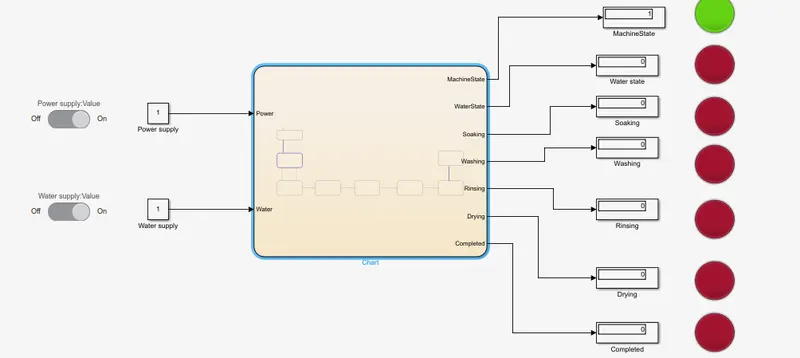
- If the power supply is available, the system gets activatedAs per 1st condition In this Model Power supply On and the system get activated and the machine state Lamp get green.
Condition 2:
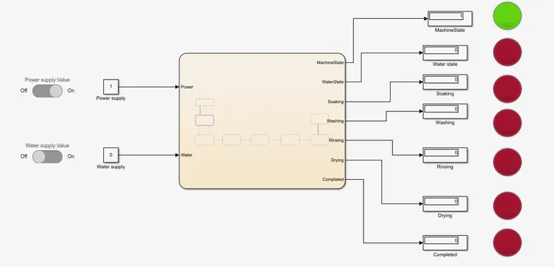
- If the Water supply is not available, stop the process & indicate through LED.
As per 2nd condition If water supply Off,Stop the Further remaining States and show in LED (As shown in Figure Below The machine state is in On but Remaining state are not started due to water supply Off and Waterstate lamp as well as all remaining lamp shows Red).
Condition3:
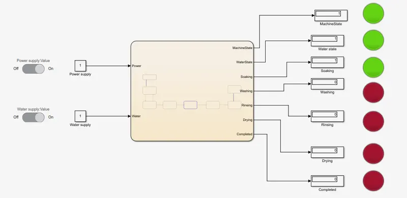
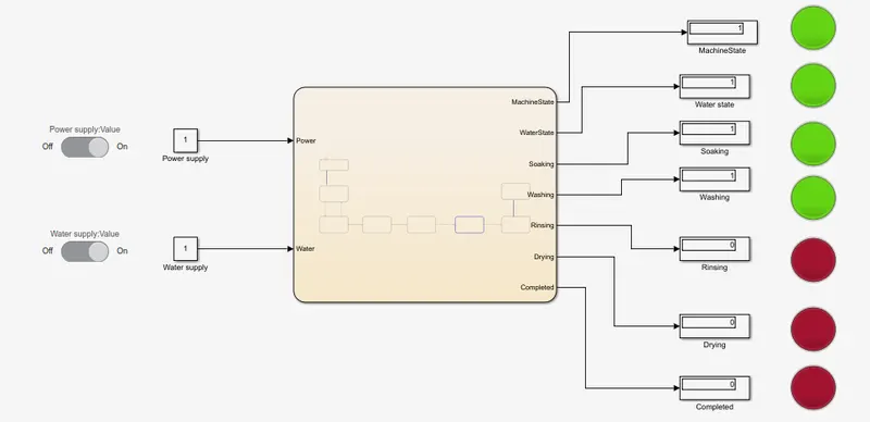
- Soaking time should be 200s followed by Washing time of 100s.
After Both The supply On The System stated as Per specified Time delay condition
After 200 sec of Soaking:
After 100s of washing:
Condition4:
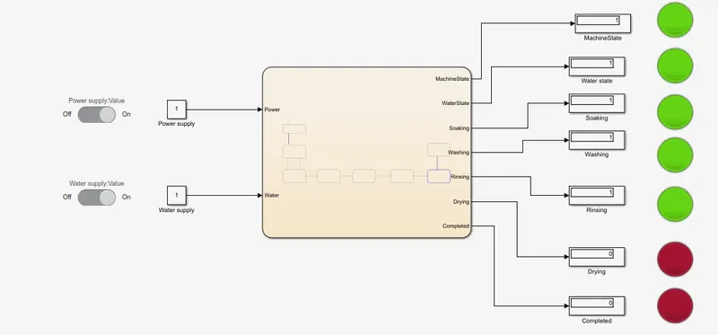
- Then rinsing happens for next 20s & dryer runs for 50s
After all the processes have completed turn on the finished LED
After 20s of Rinsing:
After 50s of Drying:
After 50 sec of drying the States are completed ,so Both Drying and Completed Lamp Gets Green as per Given Conition.
Conclusion:
Implemented the model of “washing machine” using Stateflow as per given sequence.
ANS:2
AIM
Make a Simulink chart for the “Gear shift”
Condition:
Speed Range(kmph) Gear
0 to 15 1
16 to 25 2
26 to 40 3
41 to 60 4
Above 61 5
speed input while the simulation is running & display the gear number.
To Implement Simulink Model for Gear shift
Blocks Required:
1) chart
Chart is a graphical representation of a finite state machine consisting of states, transitions, and data. We can create a Stateflow chart to define various state of a state machine.
In this chart block Represented the Condition of gear acording to speed
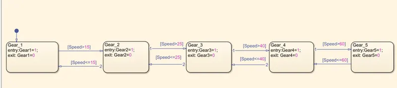
*1st state Box (Gear_1) Represents If the Speed is Less then or Equal to 15(speed<=15) The vehicle shoud Run in Gear_1 ,If Speed>15 the gear shoud shift to Gear_2
* 2nd State (Gear_2) Represents When The Vehicle speed Between 16 to 25 the Gear should be Gear_2 at Speed<=25 . If Speed>25 the Gear should shift to Gear_3
* 3rd State (Gear_3) Represents When The vehicle speed Between 26 to 40 the Gear should be Gear_3 at Speed<=40 . If Speed>40 the Gear should shift to Gear_4
* 4th State (Gear_4) Represents When The vehicle speed Between 41 to 60 the Gear should be Gear_4 at Speed<=60 . If Speed>60 the Gear should shift to Gear_5
* 5th State (Gear_4) Represents When The vehicle speed above 60(speed>60) Gear should be Gear_5
The 'Constant block' generates a real or complex constant value signal.Heare the constant Block Followed By 'Slider Block', Where We Can Change the Speed `to
check the Output in 'Display Block'. The 'Lamp Block' Represents the Gear according to Speed of vehicle Which are Followed By Display Block.
Simulink Model For Gear shift:
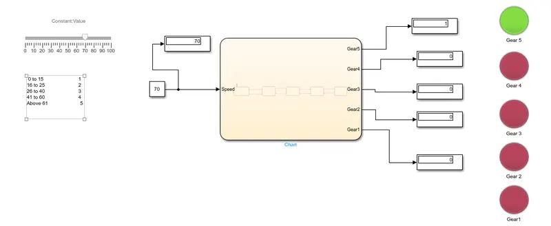
As per given condition At Gear_1 vehicle speed should 0 to 15 kmph:(At 10 kmph=Gear1)

Gear_2 vehicle speed should 16 to 25 kmph:(At 20 kmph=Gear2)
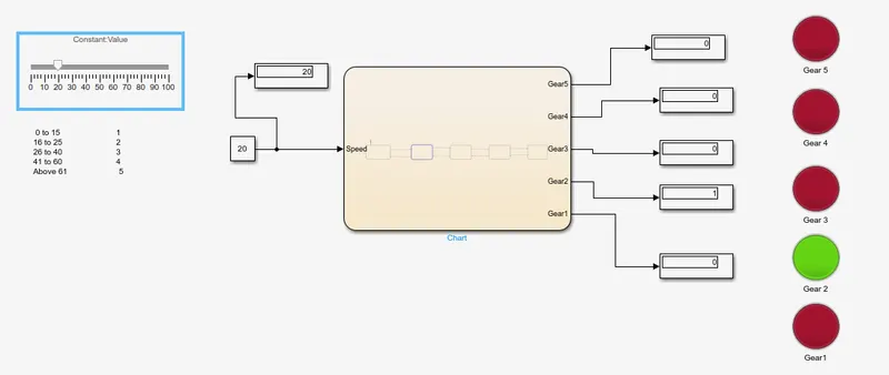
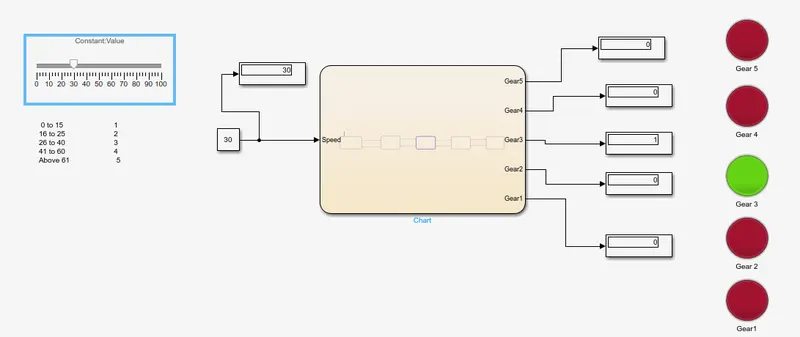
Gear_3 vehicle speed should 26 to 40 kmph:(At 30 kmph=Gear3)
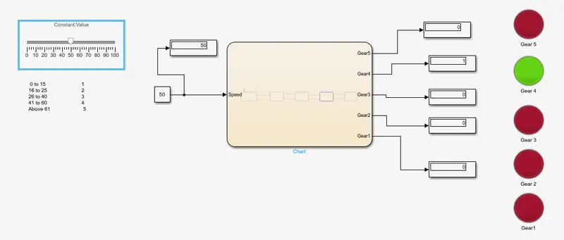
Gear_4 vehicle speed should 41 to 60 kmph:(At 50 kmph=Gear4)
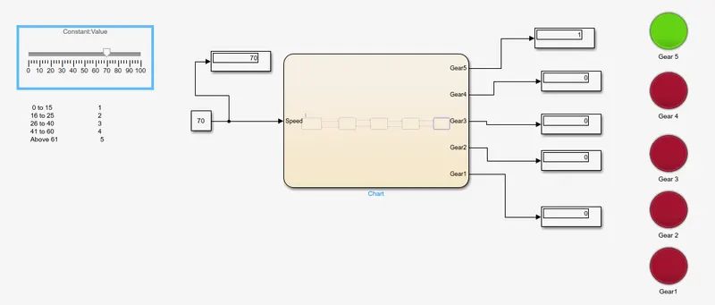
Gear_5 vehicle speed Above 60 kmph:(At 70 kmph=Gear7)
Conclusion:
From Above model The Gears are shifting Followed by the vehicle speed as input given in slider Block