Project 2 - Measuring distance of an object using ultrasonic sensor (HC-SR04)
AIM: Implementation of code for “Measuring distance of an object using ultrasonic distance sensor (HC-SR04).
- The distance travelled by a wave to the object for which we want to measure the distance using Ultrasonic Distance Sensor (HC-SR04).
- Measuring Pulse width using Input Capture Mode of Timer 1
Program :
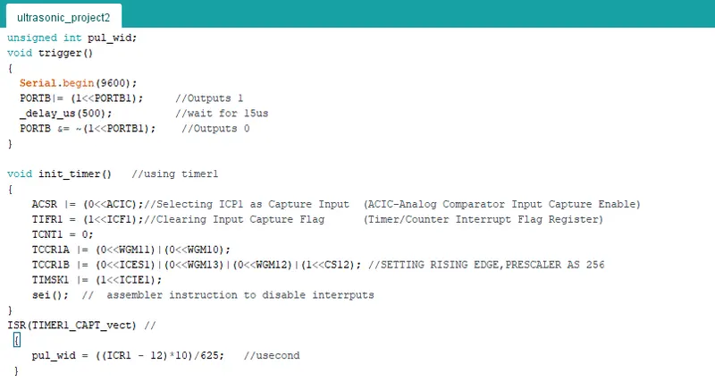
unsigned int pul_wid;
void trigger()
{
Serial.begin(9600);
PORTB|= (1<<PORTB1); //Outputs 1
_delay_us(500); //wait for 15us
PORTB &= ~(1<<PORTB1); //Outputs 0
}
void init_timer() //using timer1
{
ACSR |= (0<<ACIC);//Selecting ICP1 as Capture Input (ACIC-Analog Comparator Input Capture Enable)
TIFR1 = (1<<ICF1);//Clearing Input Capture Flag (Timer/Counter Interrupt Flag Register)
TCNT1 = 0;
TCCR1A |= (0<<WGM11)|(0<<WGM10);
TCCR1B |= (0<<ICES1)|(0<<WGM13)|(0<<WGM12)|(1<<CS12); //SETTING RISING EDGE,PRESCALER AS 256
TIMSK1 |= (1<<ICIE1);
sei(); // assembler instruction to disable interrputs
}
ISR(TIMER1_CAPT_vect) //
{
pul_wid = ((ICR1 - 12)*10)/625; //usecond
}
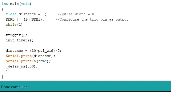
int main(void)
{
float distance = 0; //pulse_width = 0,
DDRB |= (1<<DDB1); //Configure the trig pin as output
while(1)
{
trigger();
init_timer();
distance = (30*pul_wid)/2;
Serial.print(distance);
Serial.println("cm");
_delay_ms(500);
}
}
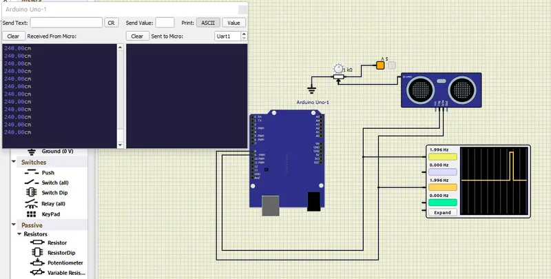
CIRCUIT:
Required Components:
1) Aurdino Uno:
Arduino is an open-source electronics platform based on easy-to-use hardware and software.
Arduino boards are able to read inputs - light on a sensor, a finger on a button, or a Twitter message - and turn it into an output - activating a motor, turning on an LED, publishing something online.
2)HC-SR04 sensor (ultrasonic distance sensor)
The HC-SR04 Ultrasonic Distance Sensor is a sensor used for detecting the distance to an object using sonar.
The one acts as a transmitter which converts electrical signal into 40 KHz ultrasonic sound pulses.
The receiver listens for the transmitted pulses. If it receives them it produces an output pulse whose width can be used to determine the distance the pulse travelled.
3)Osciloscope:
Oscilloscopes test and display voltage signals as waveforms, visual representations of the variation of voltage over time.
The signals are plotted on a graph, which shows how the signal changes. The vertical (Y) access represents the voltage measurement and the horizontal (X) axis represents time.
4)Potentiometer:
The potentiometer is a device that is used to measure the voltage or electric potential.
It provides a variable resistance when the shaft of the device is turned.
Here, we will measure the amount of resistance as an analog value produced by the potentiometer.
5)Fixed Voltage:
Here used Fixed voltage of 5 V which connected with potentiometer.
6)Ground:
Ground is where the electrical level is at 0 Volts.
It is mostly used as reference to all other electronic parts, they need one common point to operate correclty here the ground connect with potentio meter.
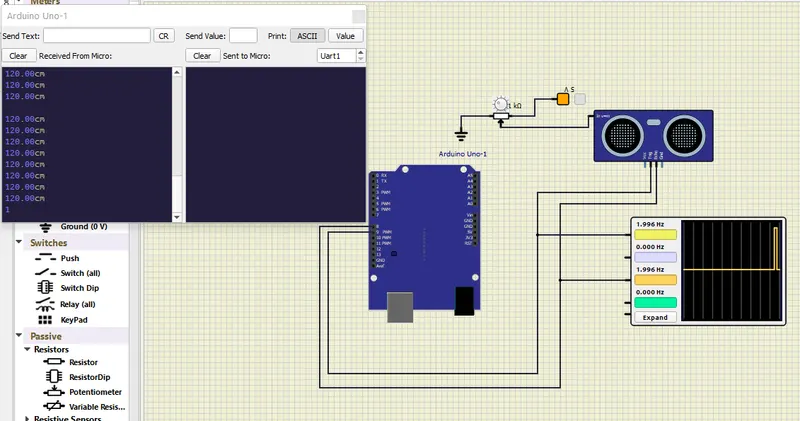
If we change the Resitance in potentiometer then simultaniously the value also changed in sirial monitor and Oscilloscope.