Week -2
Q.1 Make a Simulink model of Doorbell using solenoid block with the following details:
Ans:
AIM:
Make a Simulink model of Doorbell using solenoid block.
Doorbell :
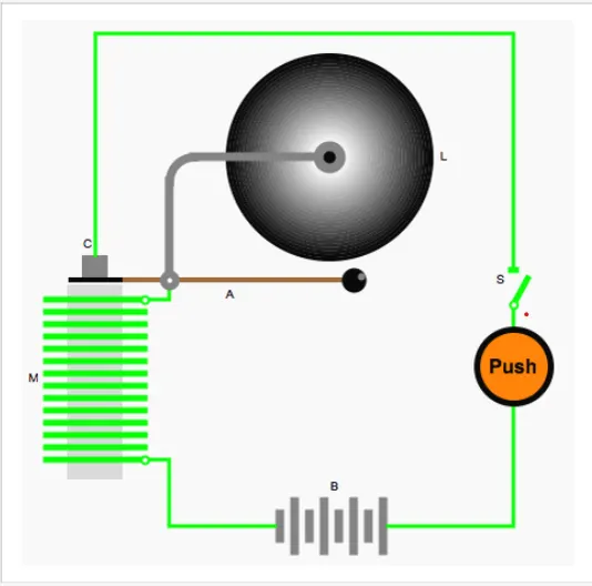
The electromagnetic doorbell is an example of a self-interrupting electrical circuit. Pushing the bell button closes the switch (S) and connects the electromagnetic coil (M) to the battery (B).
The activated electromagnet then attracts the clapper (A), which hits the bell but also interrupts the electric circuit at the contact (C). The magnet is then cut off and the clapper is released, closing the circuit. This process is repeated as long as the button is depressed.
Objectives:
1.when the switch is closed the electromagnet receives electrical power from the battery and pulls the metal arm to hit the bell producing sound.
2. The switch is closed for 2 secound ( Phase Delay) , amplitude 6 and period for 10 secound
Simulink Model :
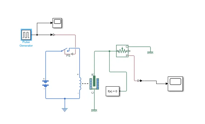
1 . In this model Pulse Generator used as input which has amplitude of 6 and frequency of 2 secound with which the input is transmitted upto 10 secound.
2.There are 2 scopes , One scope is showing the input given from pulse generator and another is showing as output of the model.
3.soilnoid is used to convert the electrical energy in to mechanical work. When an electrical current is introduced, a magnetic field forms around the coil which draws the plunger in.
4.Electrical referance and Mechanical translational referance are the reference with which system have ground source.
5. Ideal Translational motion Sensor which measures velocity or displacement of the system.
Output
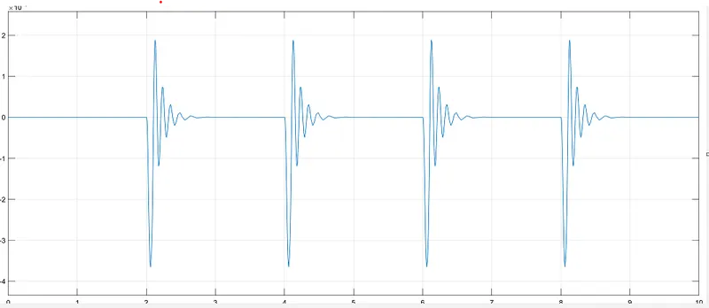
In the above there are some spikes due to electromagnetic interfarance when the switch is closed
Input signal from Pulse Generator
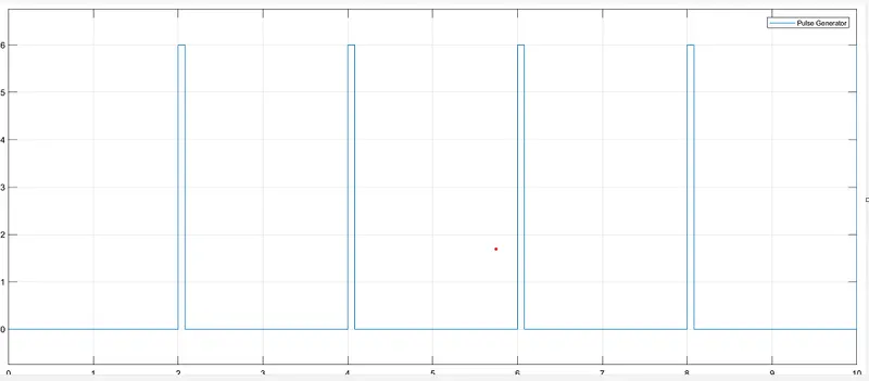
In the above graph showes the pulse given as input throuhg Pulse generator. The cycle is running for 10 secound.
Conclusion:
When switch closed ,the solenoid block receive electrical energy from battery which further convert to mechanical energy and move the plunger .and the plunger hit the bell and generate sound.
Q-2,Use a thermistor to sense the temperature of a heater & turn on or turn off the fan as per the below conditions:
ANS:
Aim:
To Use a thermistor to sense the temperature of a heater & turn on or turn off the fan as per the Given conditions.
1) Temperature source: 20 °C from 0 to 10 seconds, 27 °C from 10 to 30 seconds, 23 °C from 30 to 50 seconds
2) Fan conditions: ON if the temperature above 25 °C, OFF otherwise
Thermistor:
The thermistor works on the simple principle of change in resistance due to a change in temperature. When the ambient temperature changes the thermistor starts self-heating its elements. its resistance value is changed with respect to this change in temperature.
There are two types of thermistors:
- Negative Temperature Coefficient (NTC) Thermistor
- Positive Temperature Coefficient (PTC) Thermistor
NTC Thermistor
In an NTC thermistor, when the temperature increases, resistance decreases.
And when temperature decreases, resistance increases.
Hence in an NTC thermistor temperature and resistance are inversely proportional. These are the most common type of themistor.
PTC Thermistor
A PTC thermistor has the reverse relationship between temperature and resistance. When temperature increases, the resistance increases.
And when temperature decreases, resistance decreases. Hence in a PTC thermistor temperature and resistance are Directly proportional.
Although PTC thermistors are not as common as NTC thermistors, they are frequently used as a form of circuit protection. Similar to the function of fuses, PTC thermistors can act as current-limiting device.
Simulink model :
Explanation:
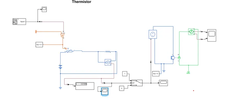
1) To represent model first a "thermistor block" taken and placed. Now a battery is connected with the thermistor to supply electrical power.
2) A resistor is connected with battery and thermistor. To know the voltage represented "voltage sensor" parallel to the resistor block and connected with a electricl referance.
3)To control the Fan at different temperature ON and OFF Used "controlled temperature source block" whis is further connected with "signal builder block" where provided the Input of the system. to convert simulink signal to PS used "simulink to PS Converter"
4) In "signal builder" Provided the Different Temperature with the interval of time as Given .
Signal builder Input
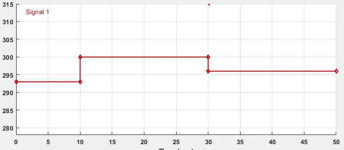
- From 0-10 sec 20 °C = 293 k
- From 10-30 sec 27 °C = 300 k
- From 30-50 sec 23 °C= 296 k
5)A "scope" represented to know the signal from signal builder.
The signal builder Output.
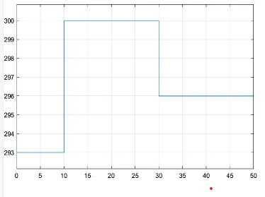
The Output From Thermistor.
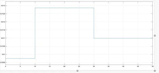
From This graph we found That At the Temperature Of 293 k The voltage In Between 0.0095 - 0.01 , at temperature 300k The voltage between 0.0125-0.013
and at the Temperature 296 k voltage near To 0.011.
As per Condition Fan shoud be ON if the temperature is more then 298 k .
6) Represented a "Switch Block" an and and provided the signal according to the condition provided. (thresshold Value-0.011) and anothor two port connected with constant block with the value 0 and 1 respectively.
Now the output we get.
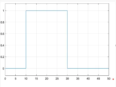
7) To represent Fan condition we need to further connect "Voltage sensor" , "DC motor" and "Ideal Rotational Motion sensor" to the switch.
Where we Fixed the Logic As The switch will ON when the Voltage is 0.01106 (298 k). If the Temperature More then 298 k the switch will on and the fan will get ON.
Conclusion:
Here we acchived The different Voltage with Given Temperature source as input.
and when the tempretaure get mor then 298 k the Fan gets On.